

BMCU-C (370 Hall Sensor Version) Assembly Guide
Preface
This guide was entirely written by wanzi 😊
It is intended for the assembly of BMCU-C v0.2 channel modules.
If you don’t yet have the necessary parts, please refer to the Bill of Materials to purchase them 🛒
This article was written on my birthday (2025.4.16) 🎉
If you found this guide helpful, feel free to support the wiki with a donation 💖
Preparation Before Assembly
Bundled resources for this tutorial: Coming soon. Please refer to the group file section for now 📁
- A fully soldered BMCU "Hall version" PCB, ensuring no soldering defects (e.g. cold joints, missing solder, bridges, or wrong connections). Flash the firmware—refer to the group file section for instructions on how to flash the firmware.
- The firmware flashed must be suitable for the Hall sensor version. As of 2025.4.16, the latest available firmware is
BMCU-C-4-13 Test - 3D printed outer shell
- 3D printed magnet polarity detector
Main Assembly
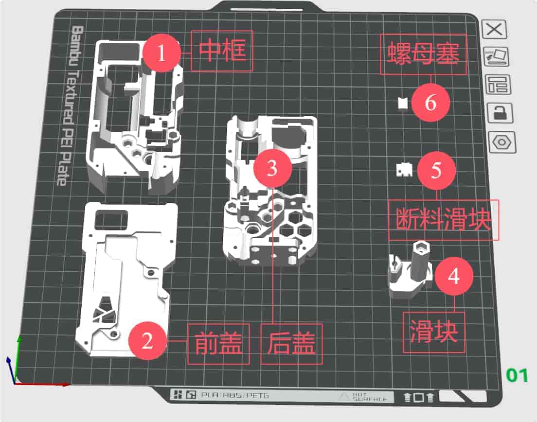
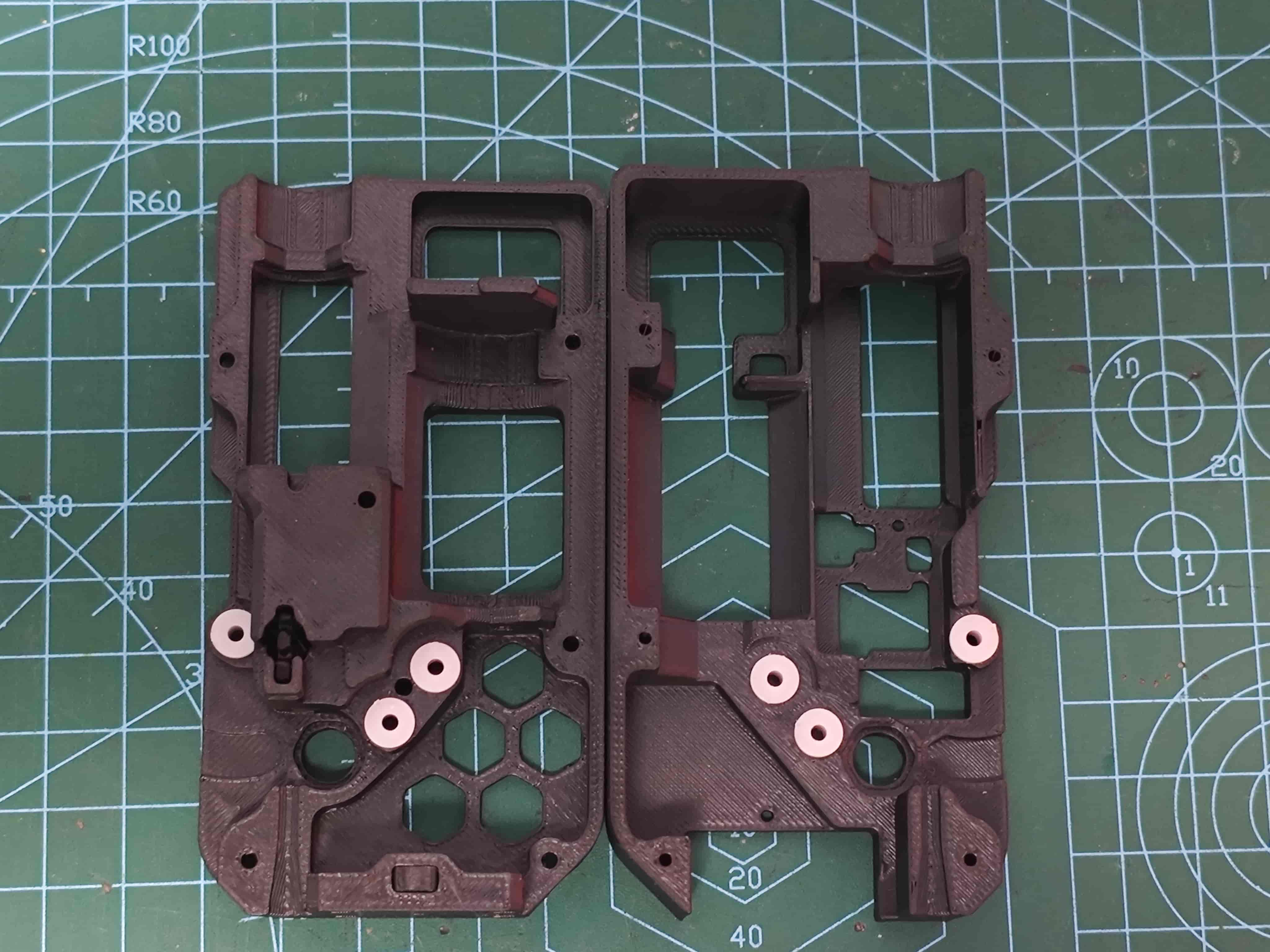
Component Names Overview
Insert the 62B Bushing
Insert the 62B bushings into the back cover and the mid-frame as shown.
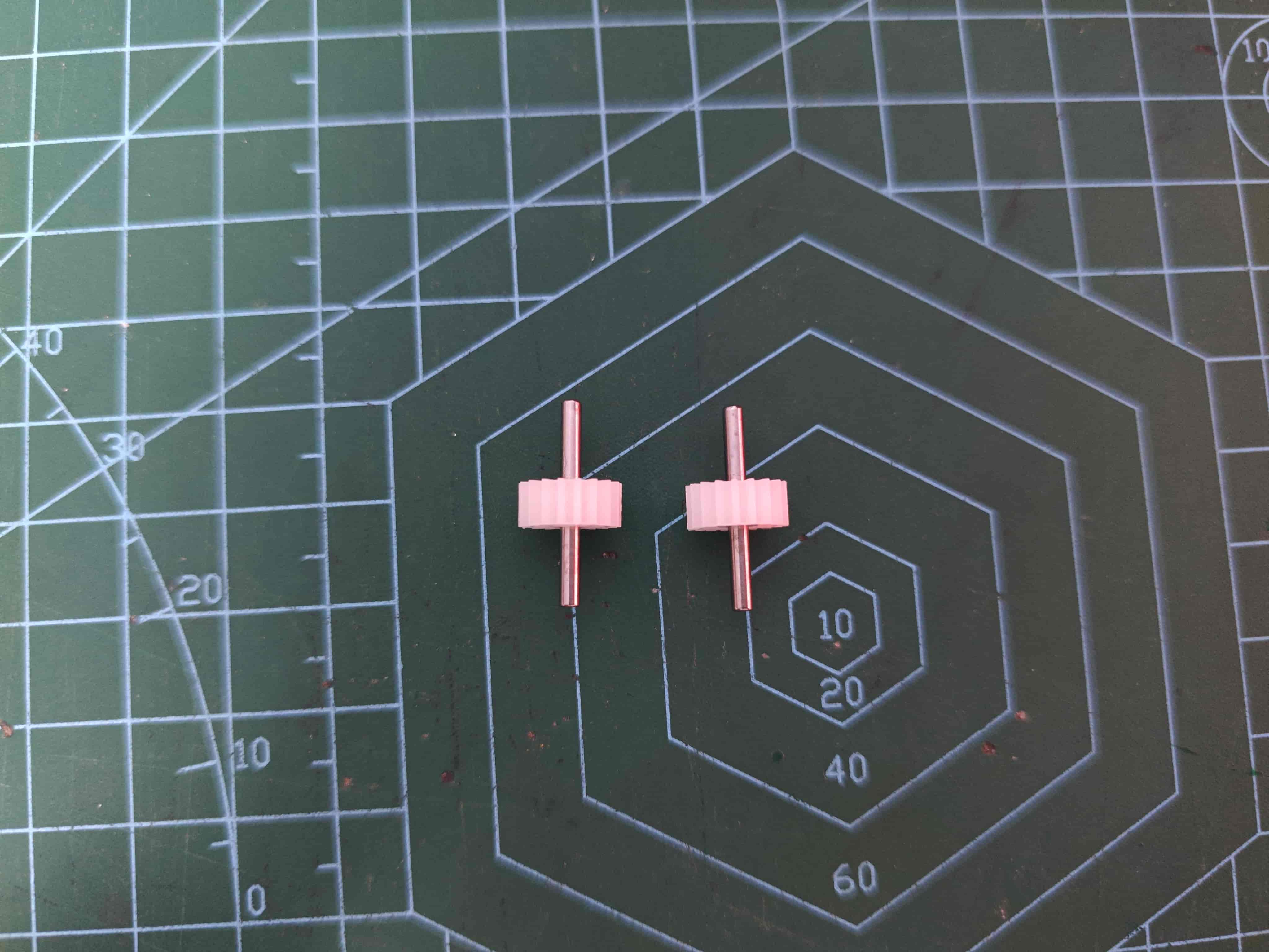
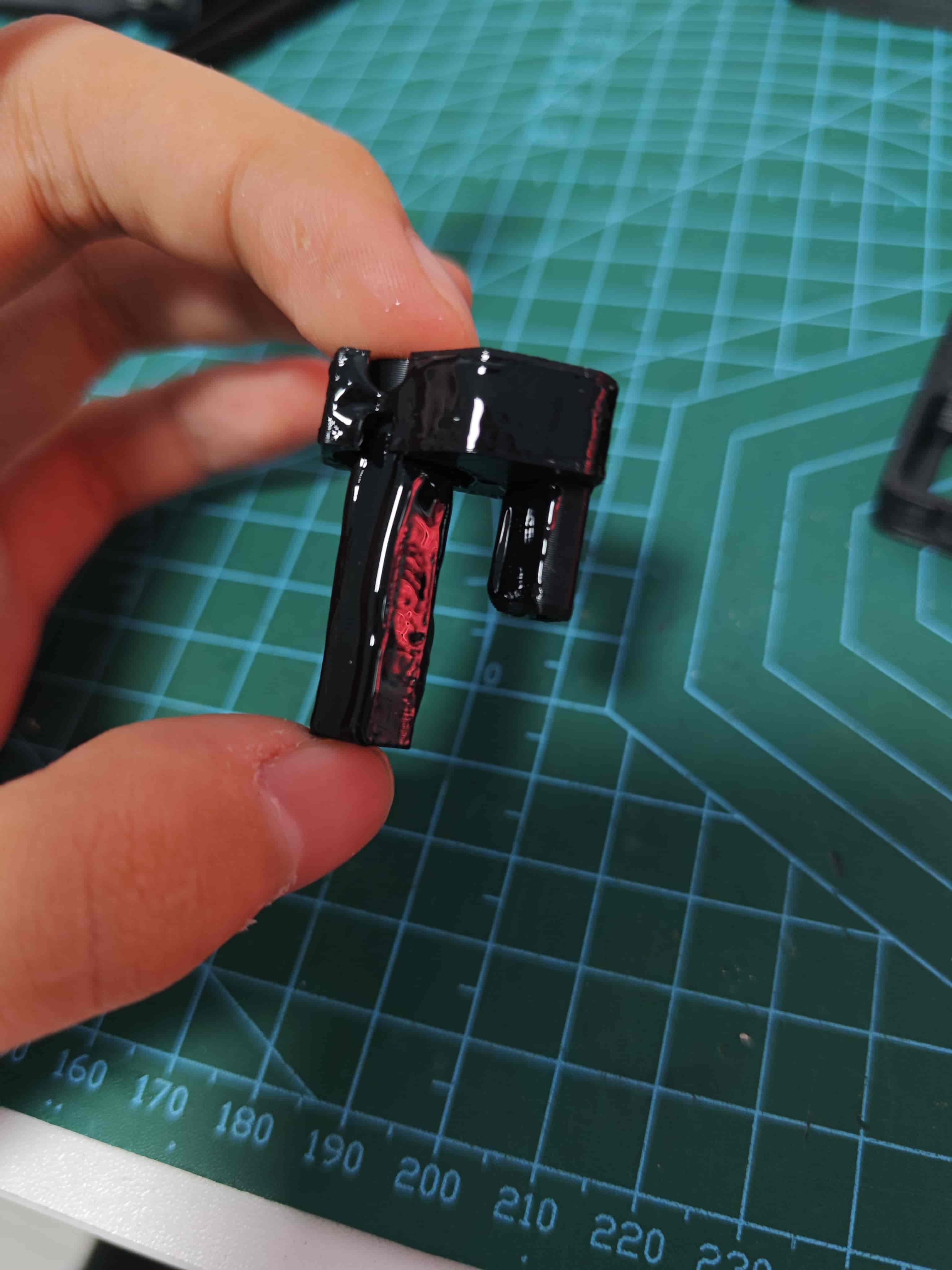
Assemble the D2*20 Shaft and 182A Gear
Ensure both ends are protruding equally.
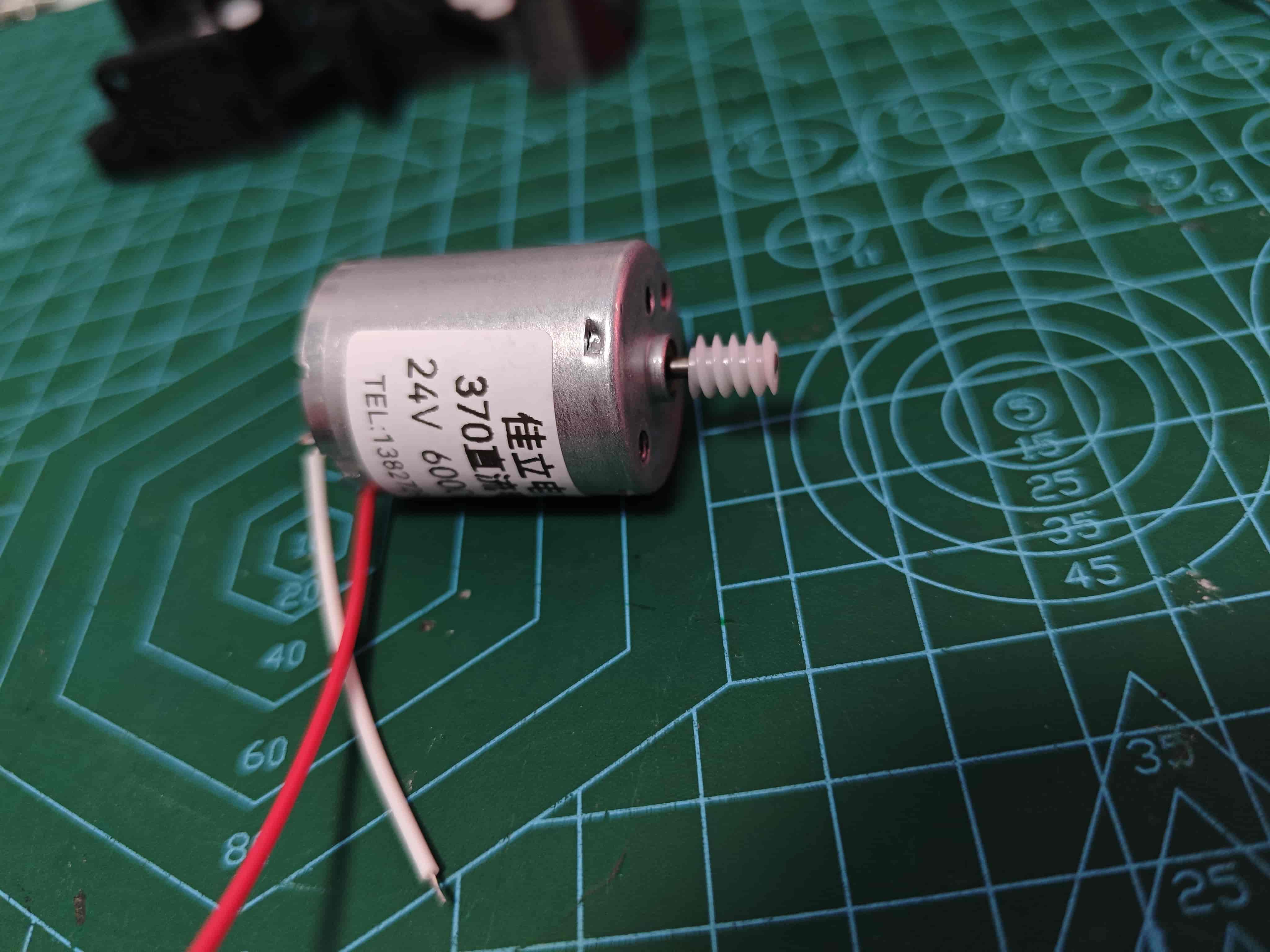
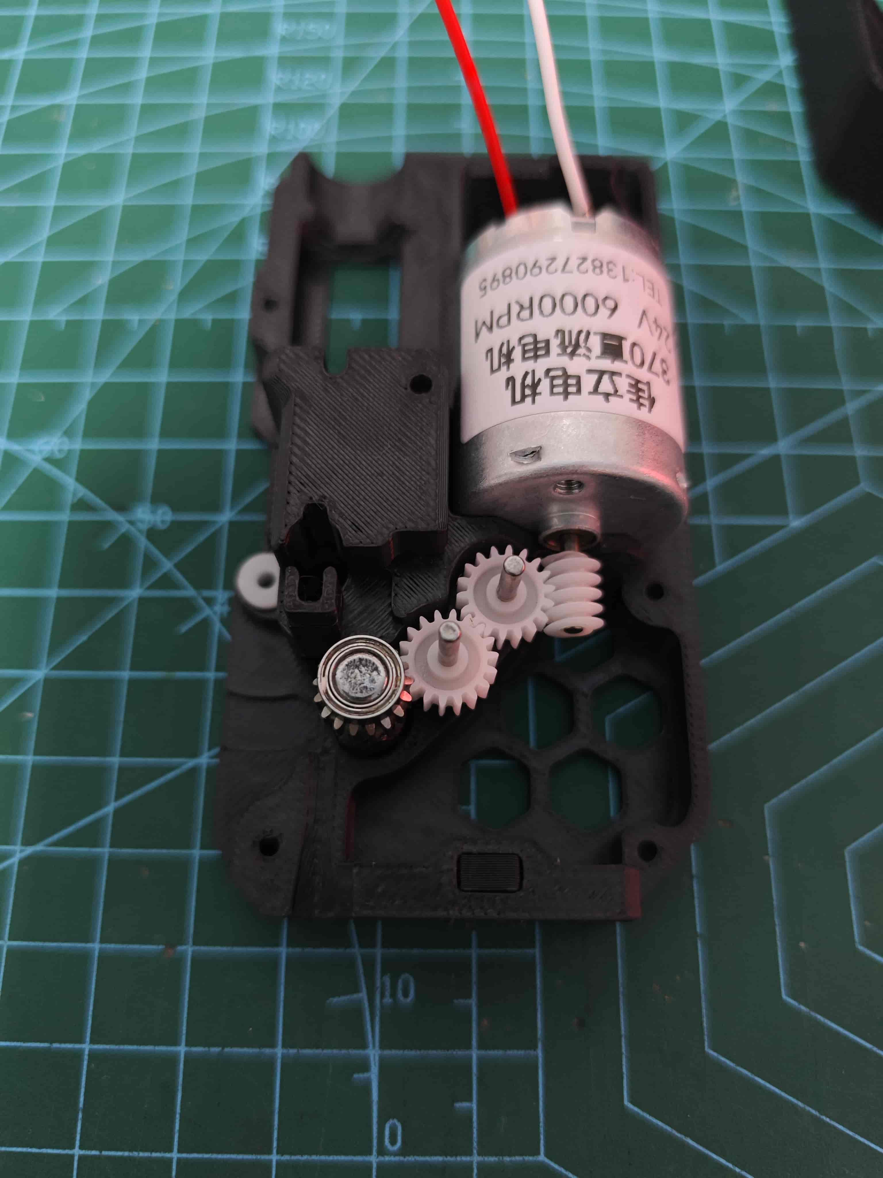
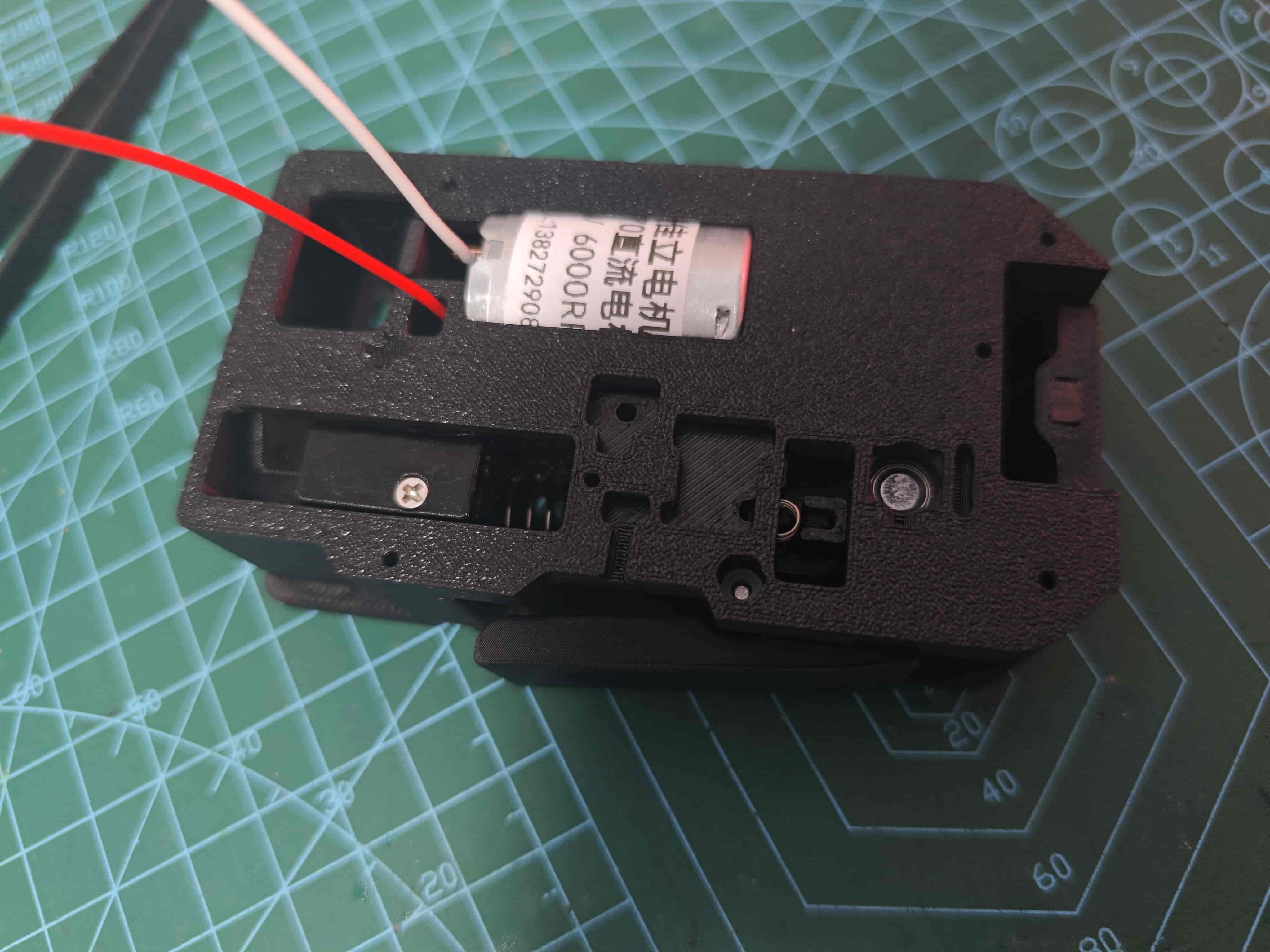
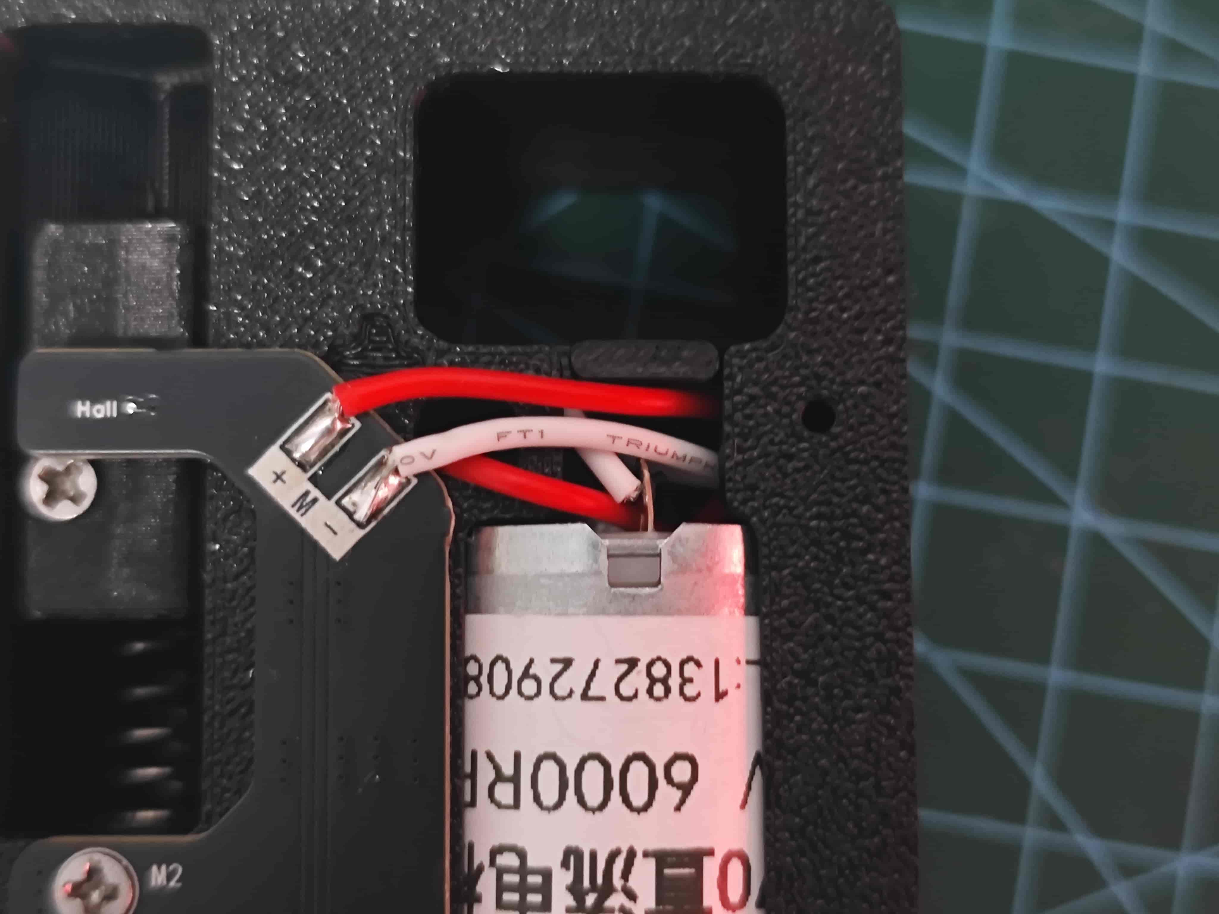
Install Worm Gear on 370 Motor and Solder Motor Wires
Align the motor shaft flush with the worm gear. Optionally, apply 502 glue for reinforcement.
The terminal with the red dot is the positive pole.
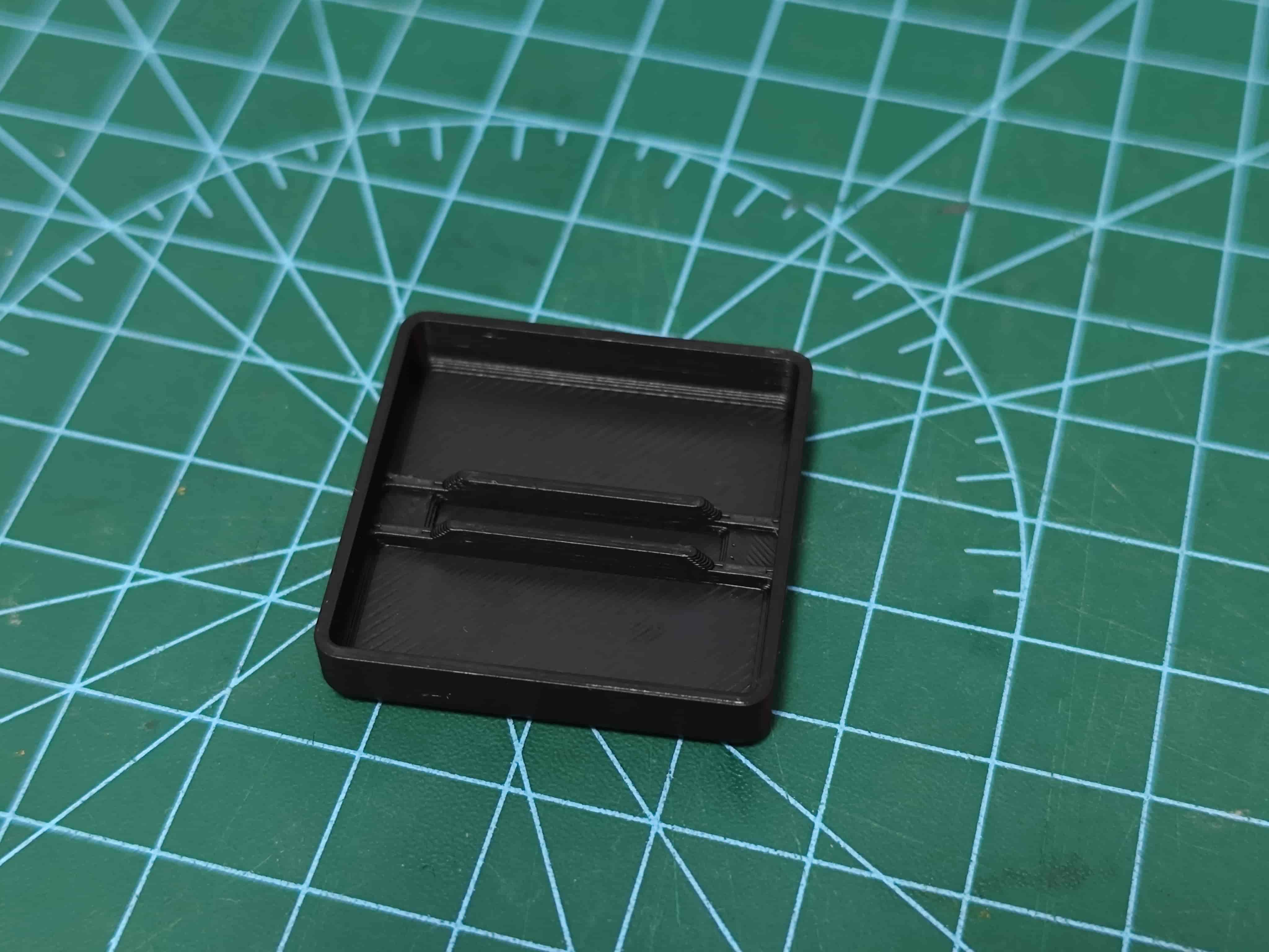
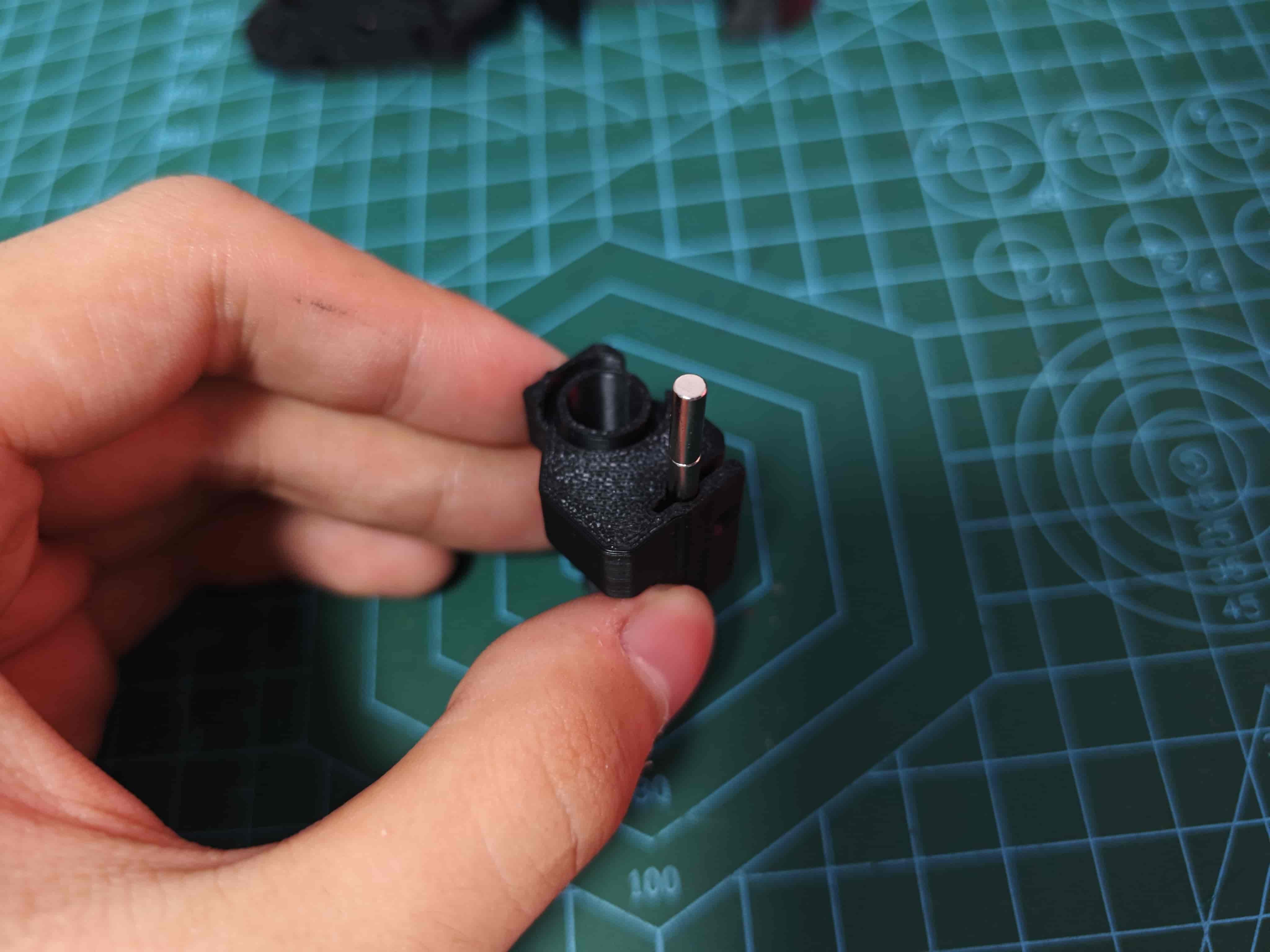
Determine the Polarity of the Slider Magnets
TIP
Although there are various ways to check polarity, please consider printing the magnet polarity detector I designed. This helps me earn Bambu Lab credits as a motivation to maintain the wiki. Thank you for your support! 🙏
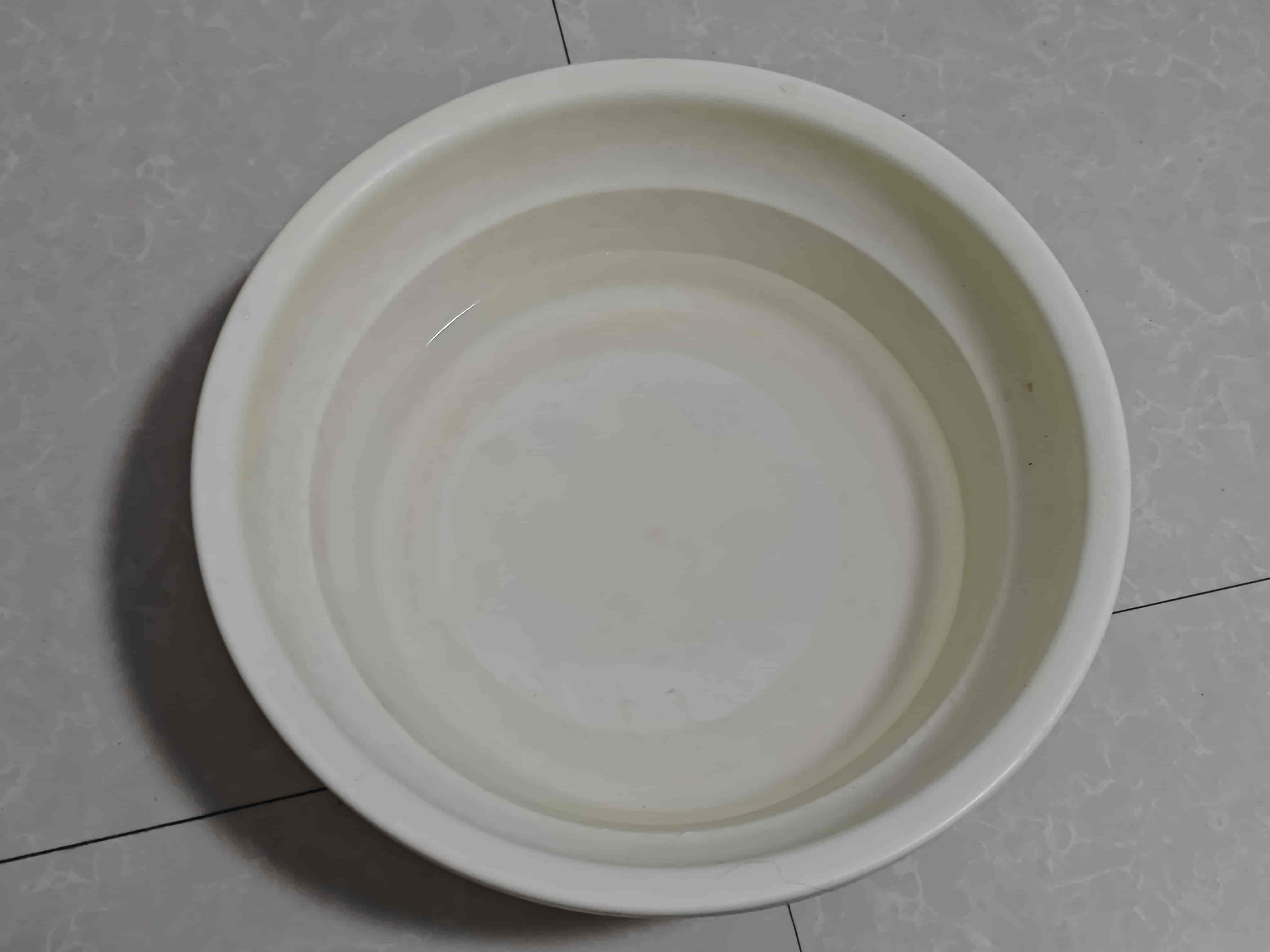
Prepare a container (bowl, dish, basin, etc.) and fill it with some water 💧
Attach two D3*10 magnets together, place them in the polarity detector, and float it on the water.
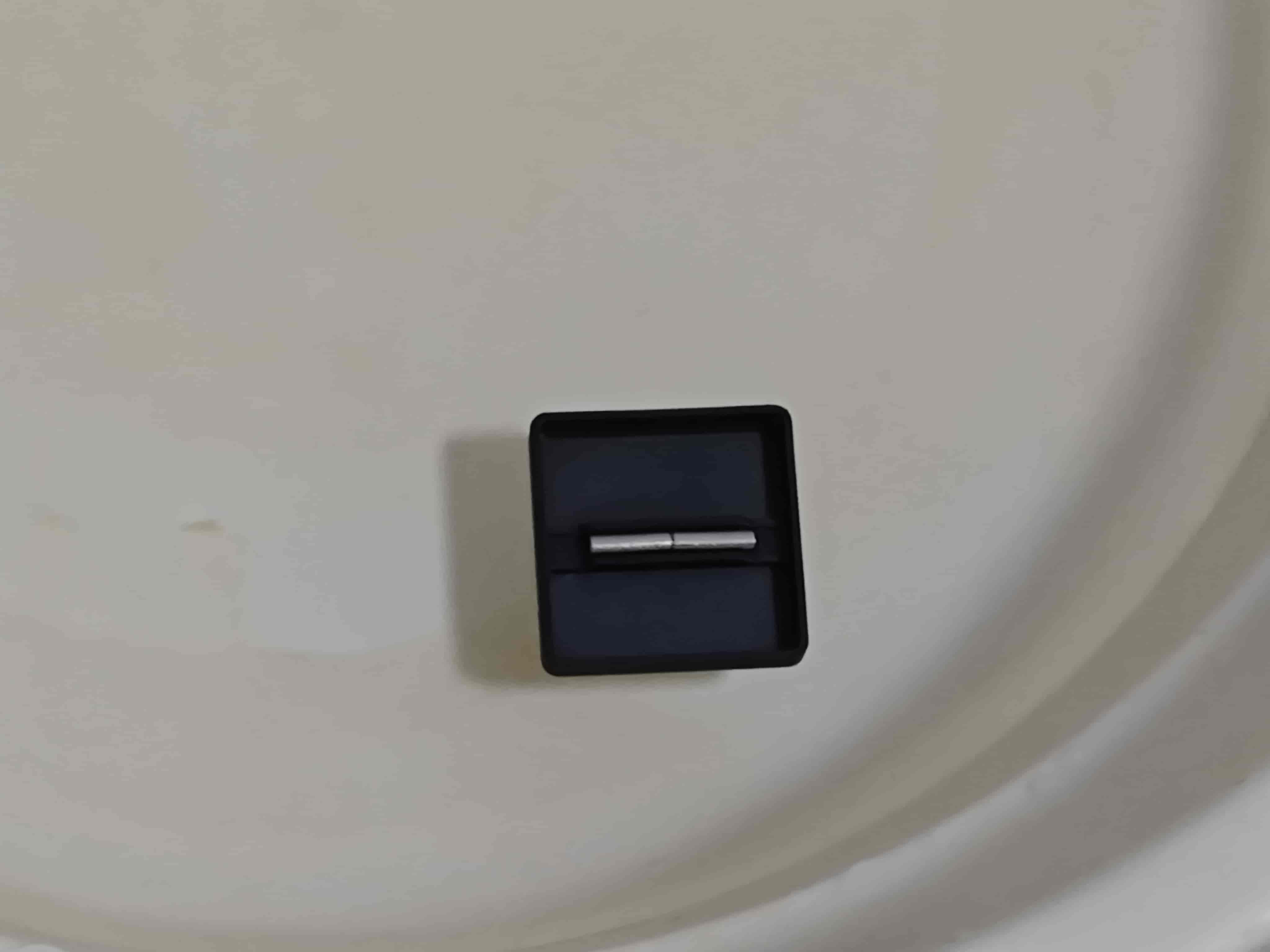
Once stabilized, the side facing south is the South Pole, and the other is the North Pole 🧲
Insert Magnets into Slider
Align the slider as shown. Insert the magnet with its South Pole facing downward (toward the pneumatic joint side).
Important: The magnet must be centered exactly in the magnet slot of the slider ⚠️
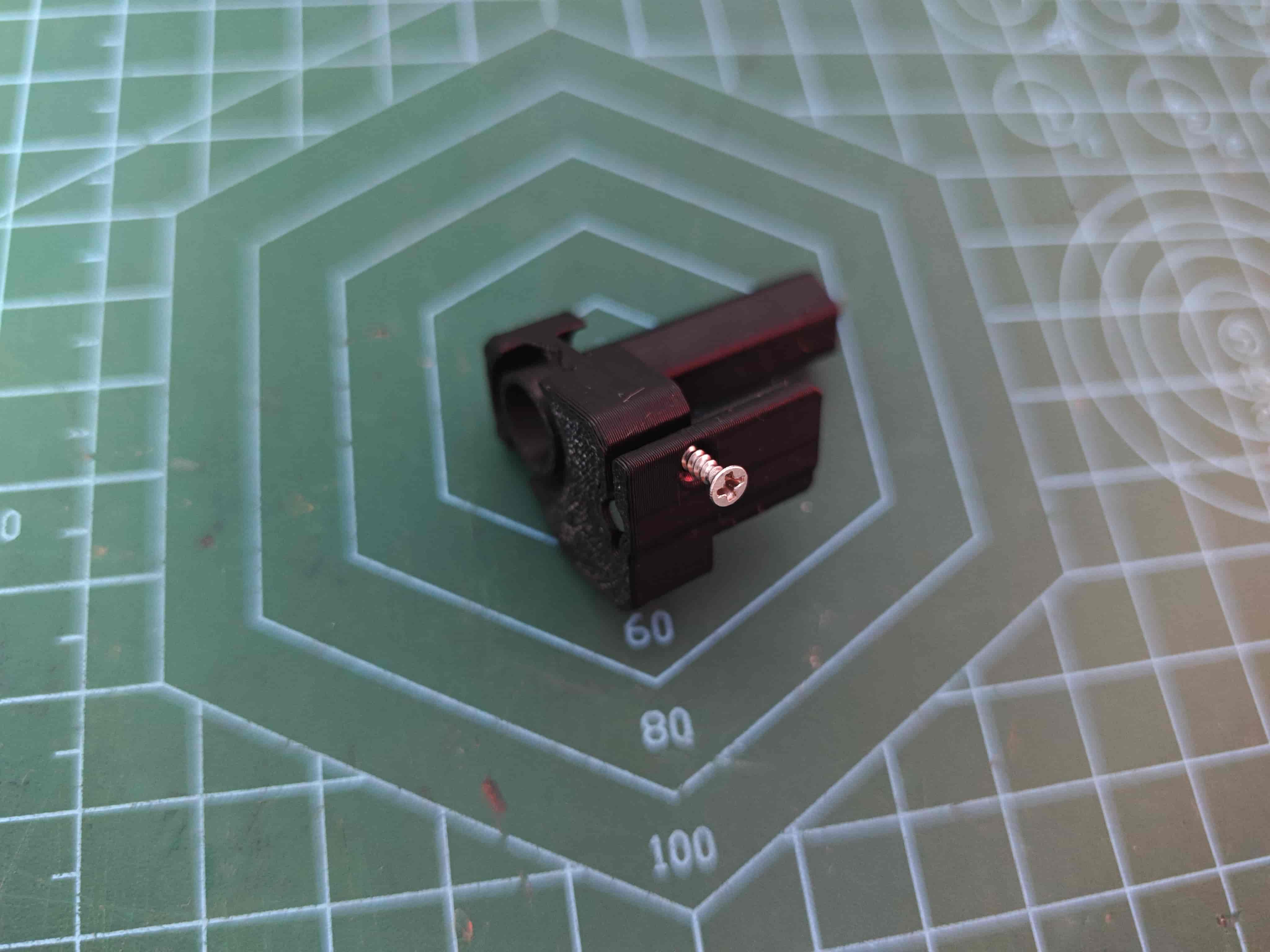
Secure Slider Magnet
Use an M2*8 self-tapping screw to fasten the magnet.
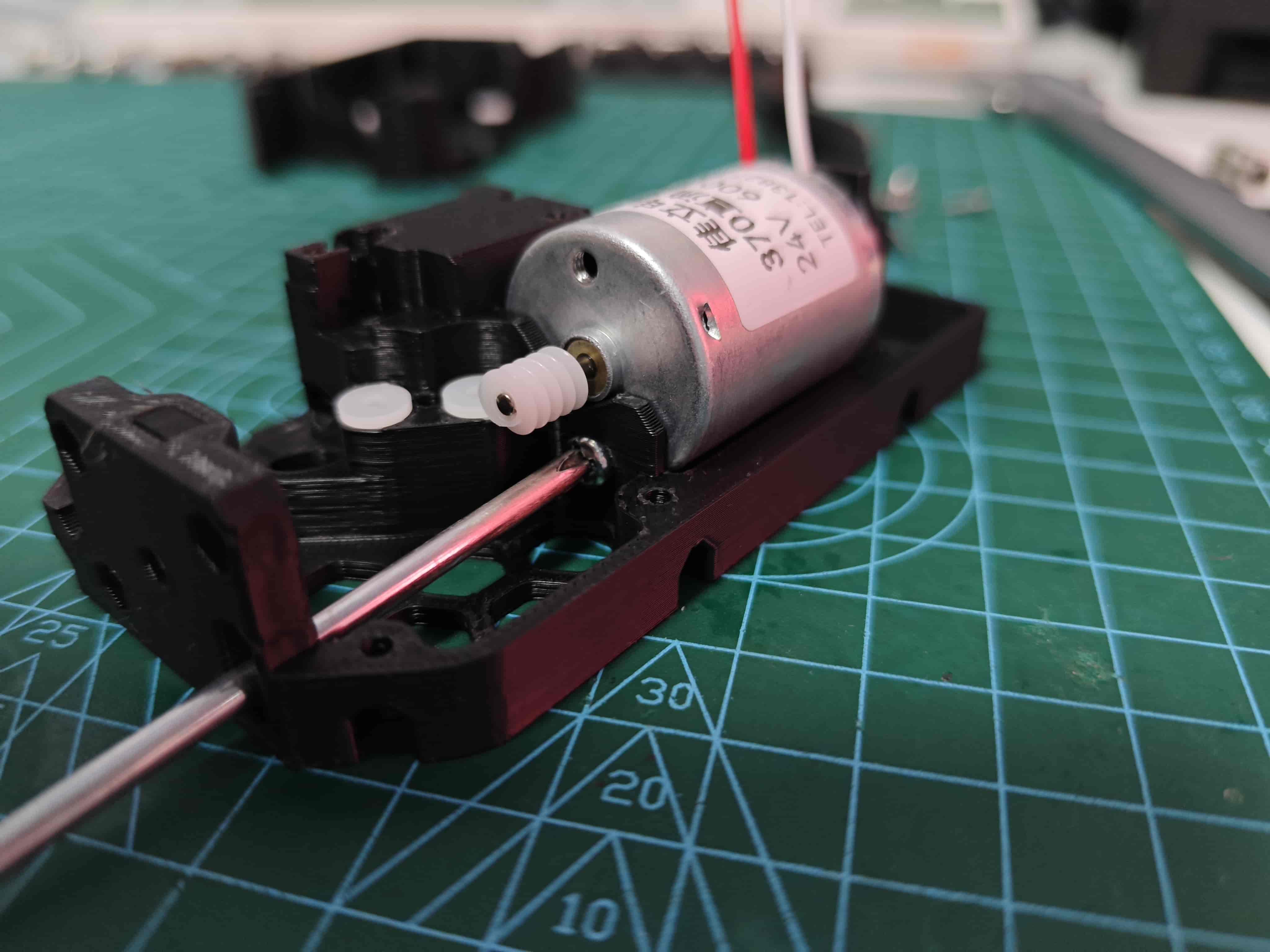
Install the Motor
Insert the motor into the designated position and fix it with one M3*5 machine screw.
Install the Nut and Nut Retainer
Insert an M3 hex nut into the slot and use a retainer to secure it (no image available, but it should be intuitive).
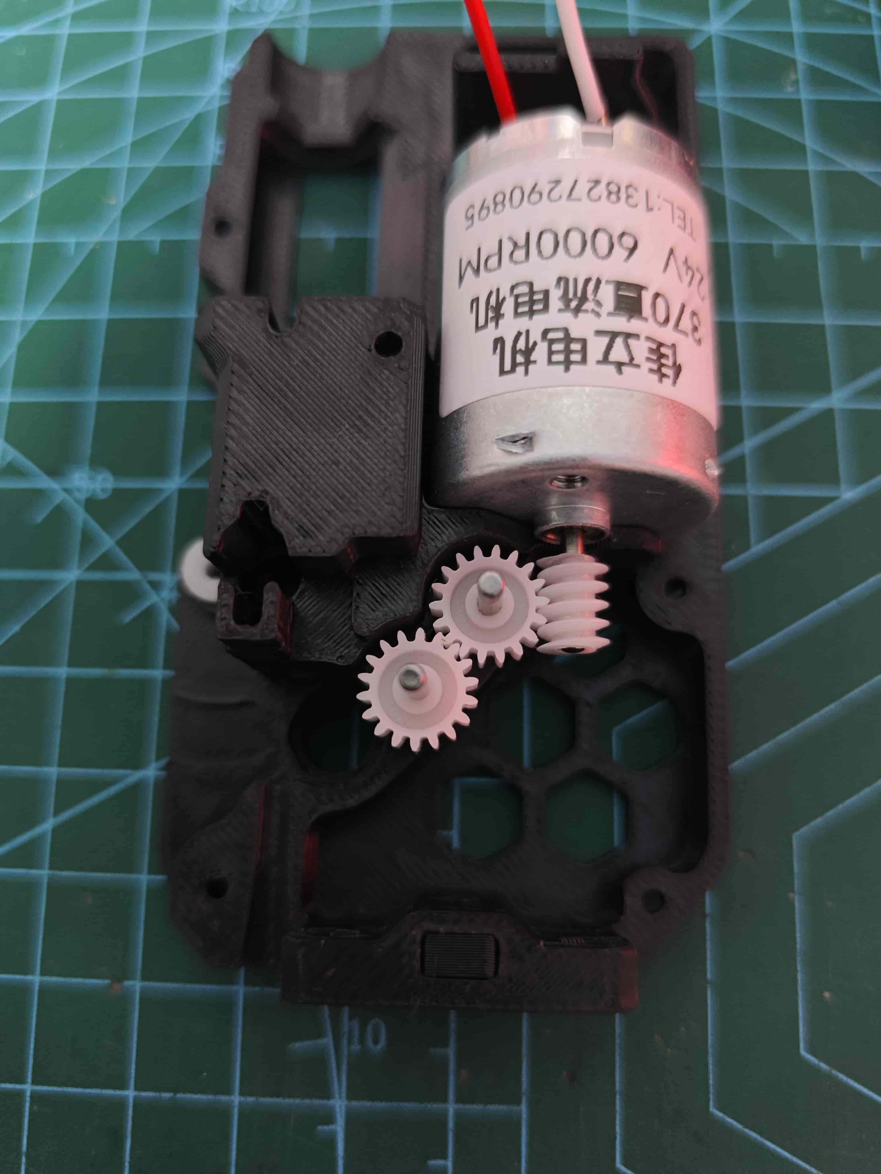
Insert the Gear
Assemble BMG Drive Gear
Refer to the corresponding section in the 370 steel ball version guide.
Assemble BMG Idler Gear
Refer to the corresponding section in the 370 steel ball version guide.
Insert BMG Drive Gear
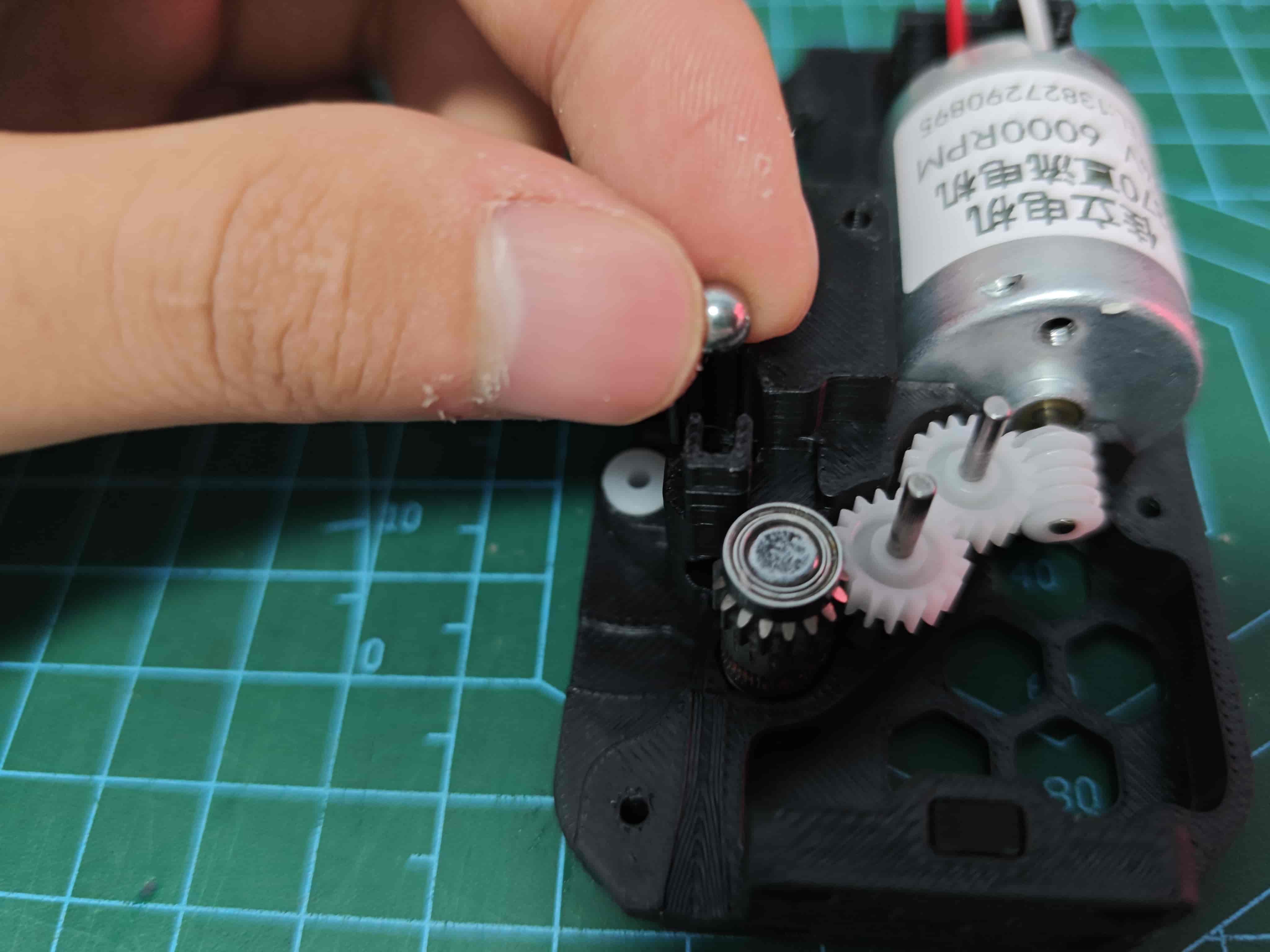
Insert Steel Balls
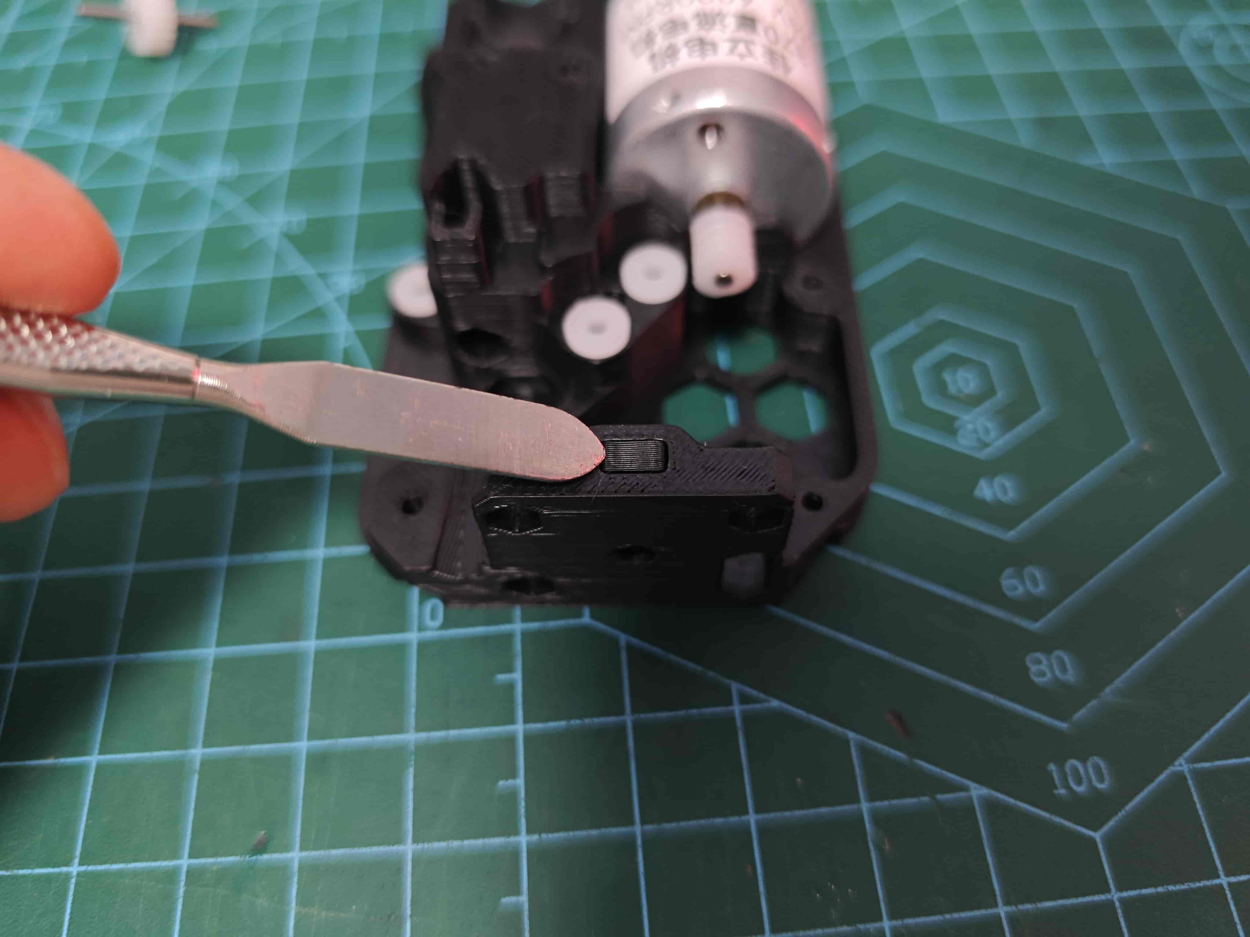
Insert Jam Sensor Slider
Make sure to align the slider in the correct orientation.
Apply Lubricant
Lubricate the gears (you may take them out, apply grease, and reinsert them. No need to lubricate the BMG gear).
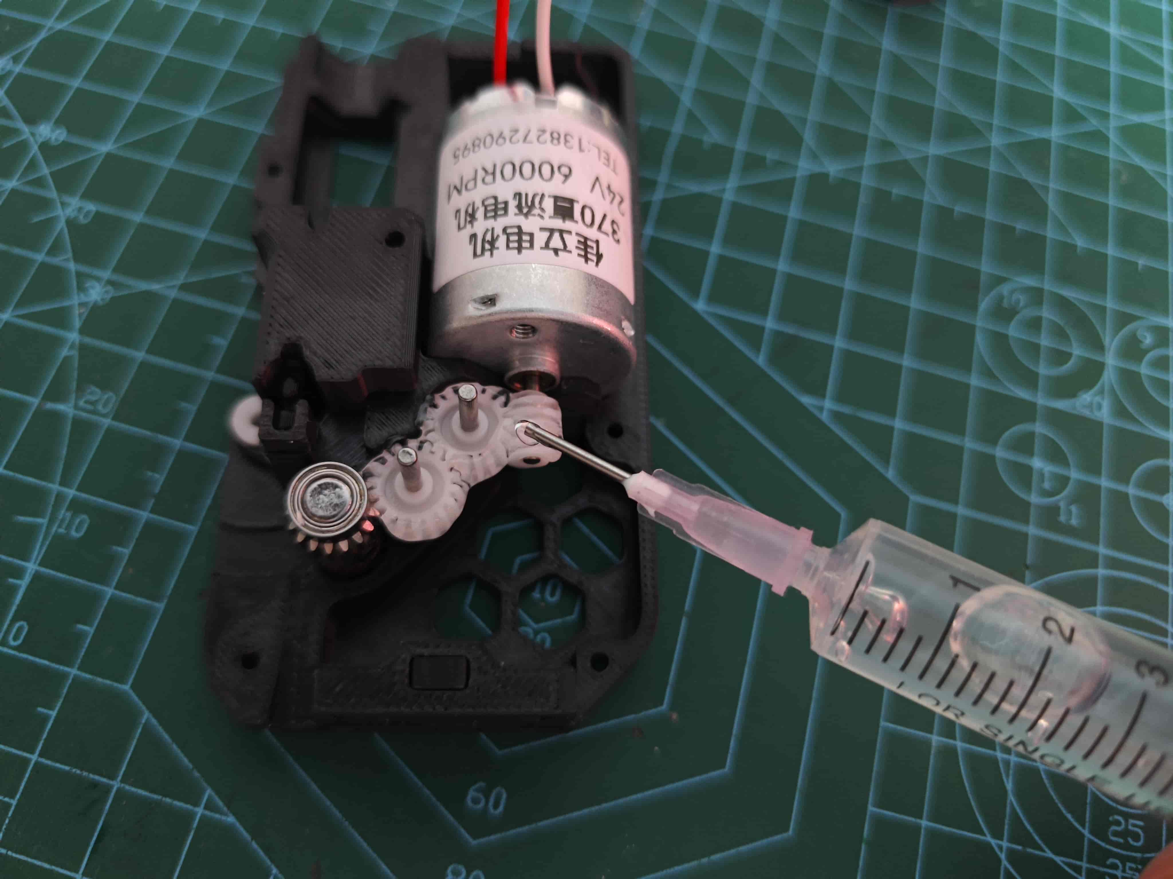
Optionally lubricate the slider.
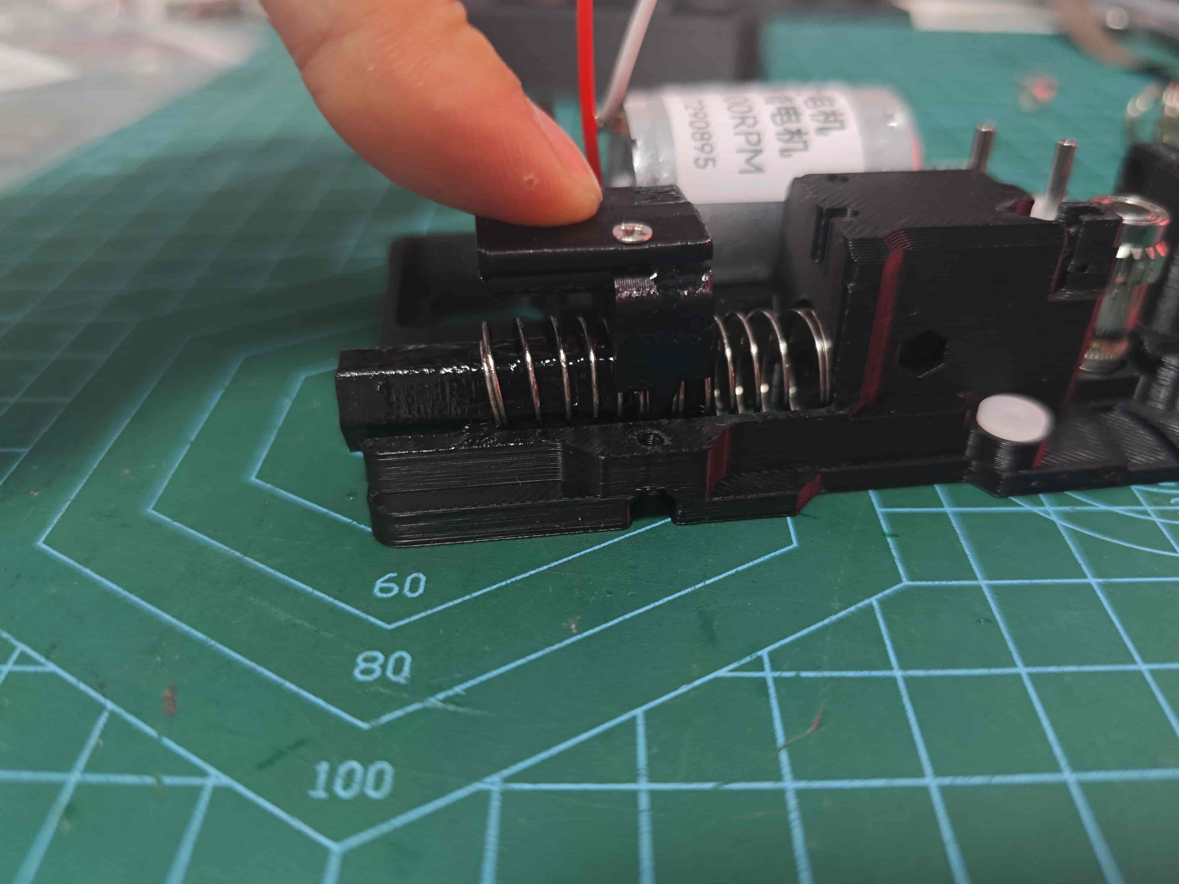
Install Slider Springs
Insert two 0.8*12*25 springs into both ends of the slider and fit them in place.
(Note: I temporarily used 0.7*12*30 from the 370 version for demonstration. You won't encounter such difficulty during installation.)
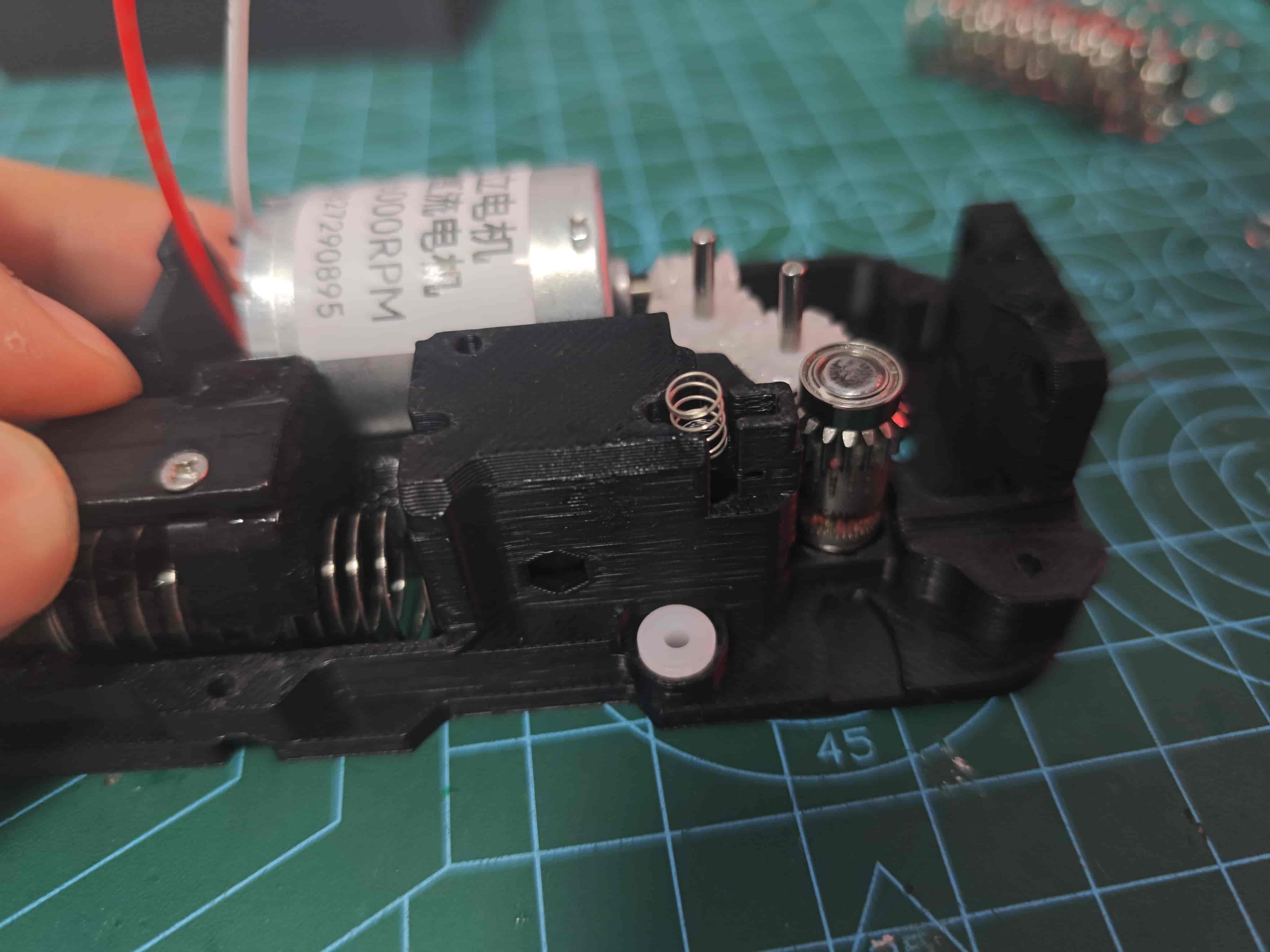
Install Jam Sensor Spring
Insert a 0.3*4*5 spring above the jam sensor slider.
Install the Mid-frame
Attach the mid-frame onto the back cover. Ensure the magnet-equipped part of the slider goes through the frame.
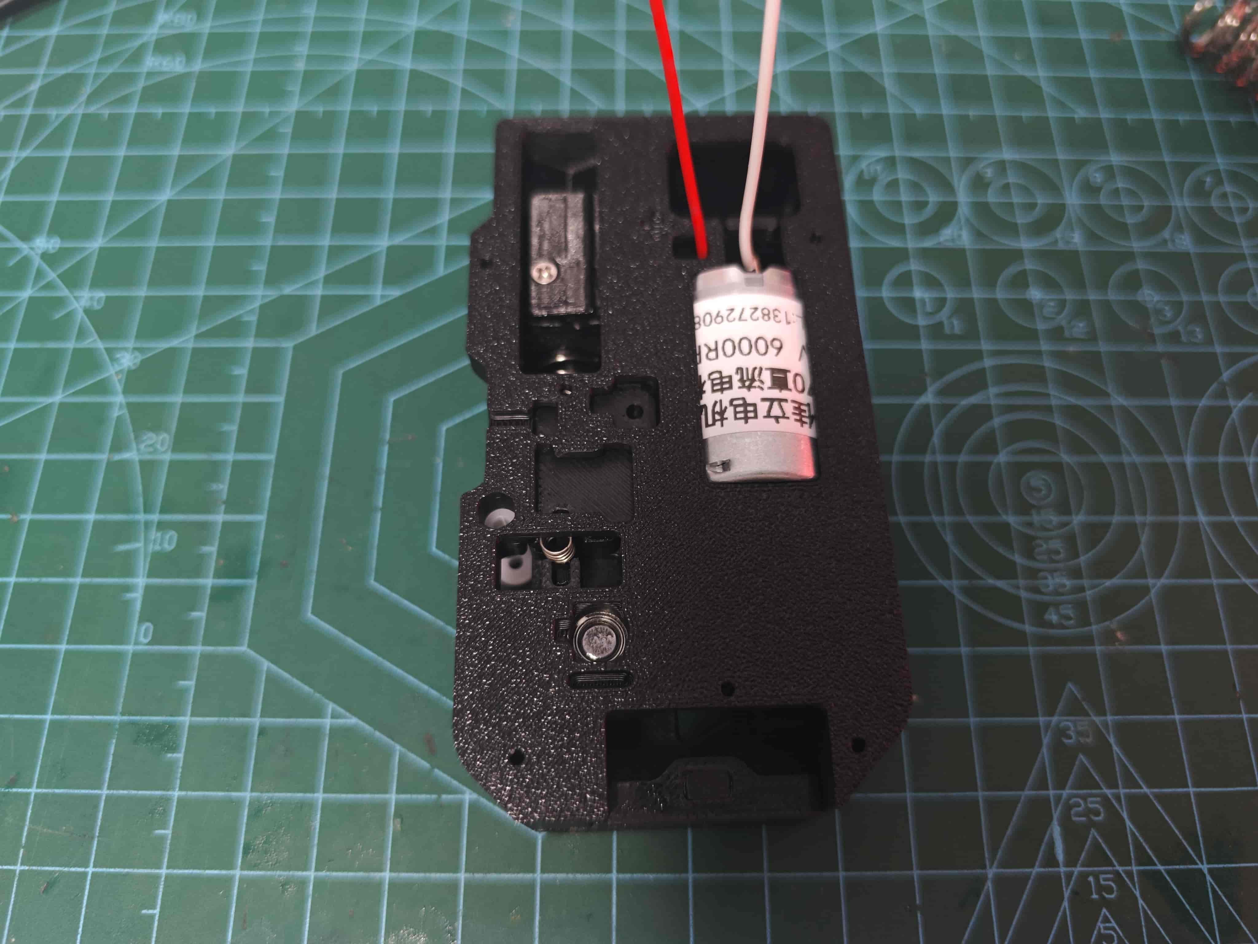
Secure it with five M2*8 self-tapping screws.
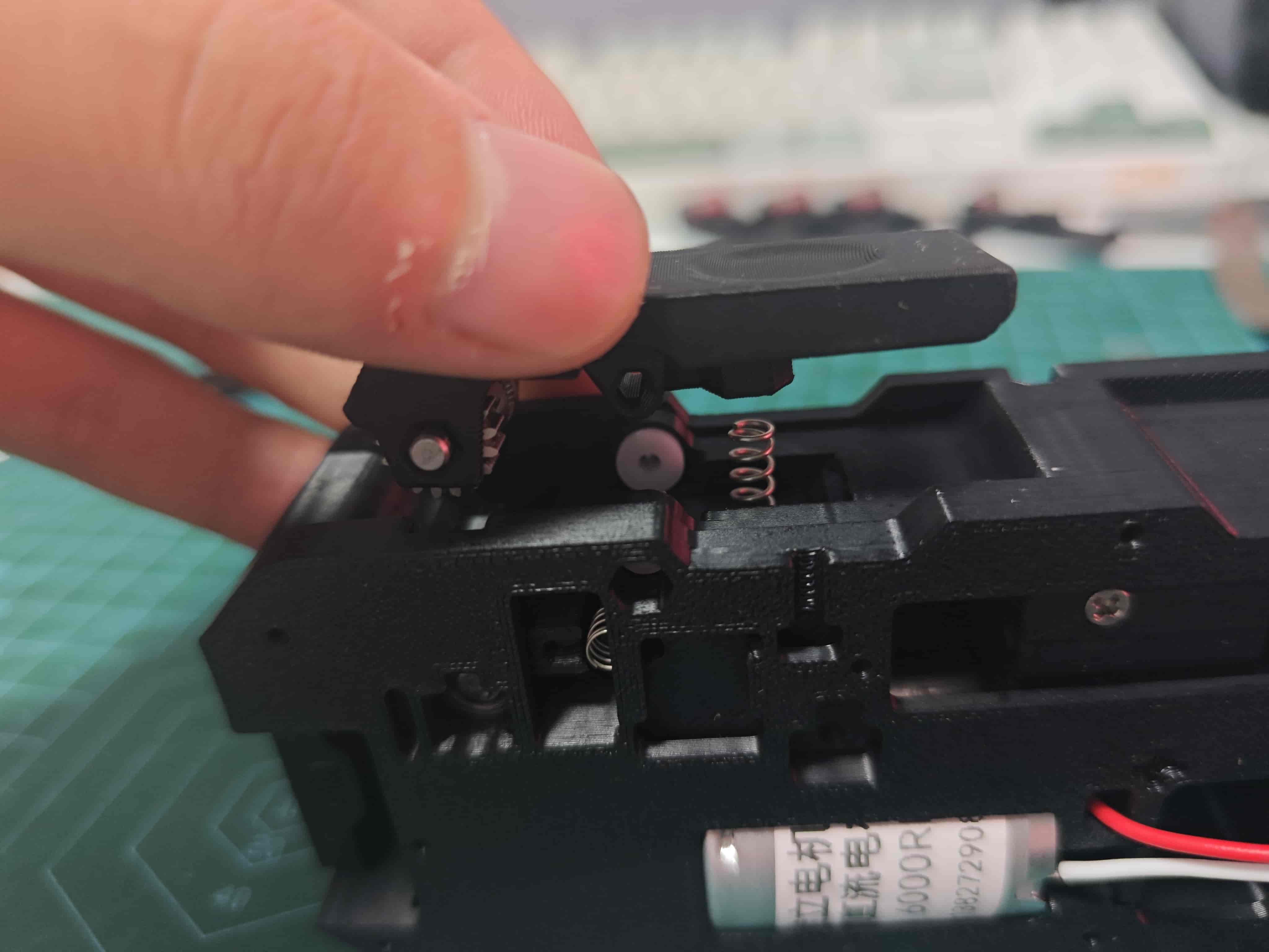
Install the Lever
Insert a 0.6*4*10 spring into the designated slot, then place the lever.
TIP
If your filament guide or spool has high resistance, or you’re using a P1 printer, use this model under the spring to increase clamping force.
Manually press the lever and insert a D2*20 shaft.
Press it in with force using a tool, then use a screwdriver to push it firmly into the recess.
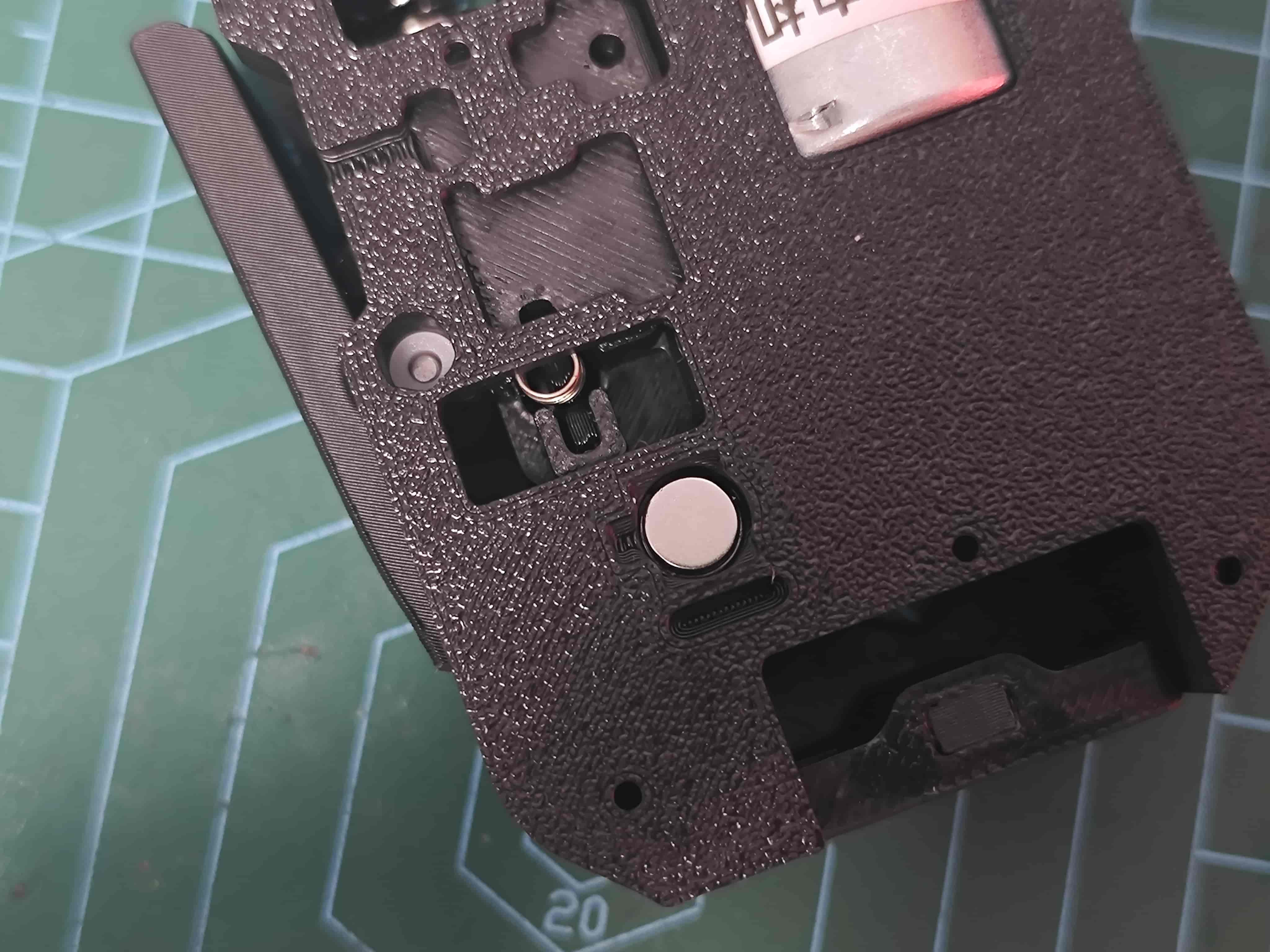
Install Radial Magnet
Attach a D6*2.5 radial magnet above the BMG drive gear. Ensure it’s not obstructed and rotates with the gear (critical).
Tip
At this point, insert filament and use a 12V~24V power supply to test:
- whether filament can be pulled through
- whether the magnet rotates correctly
- and whether lubricant is evenly distributed
TIP
You may insert a fiber optic cable into the small hole beside the slider for light guidance. Insert fully and trim the excess ✂️
Install the Sub-board
Place the sub-board as shown.
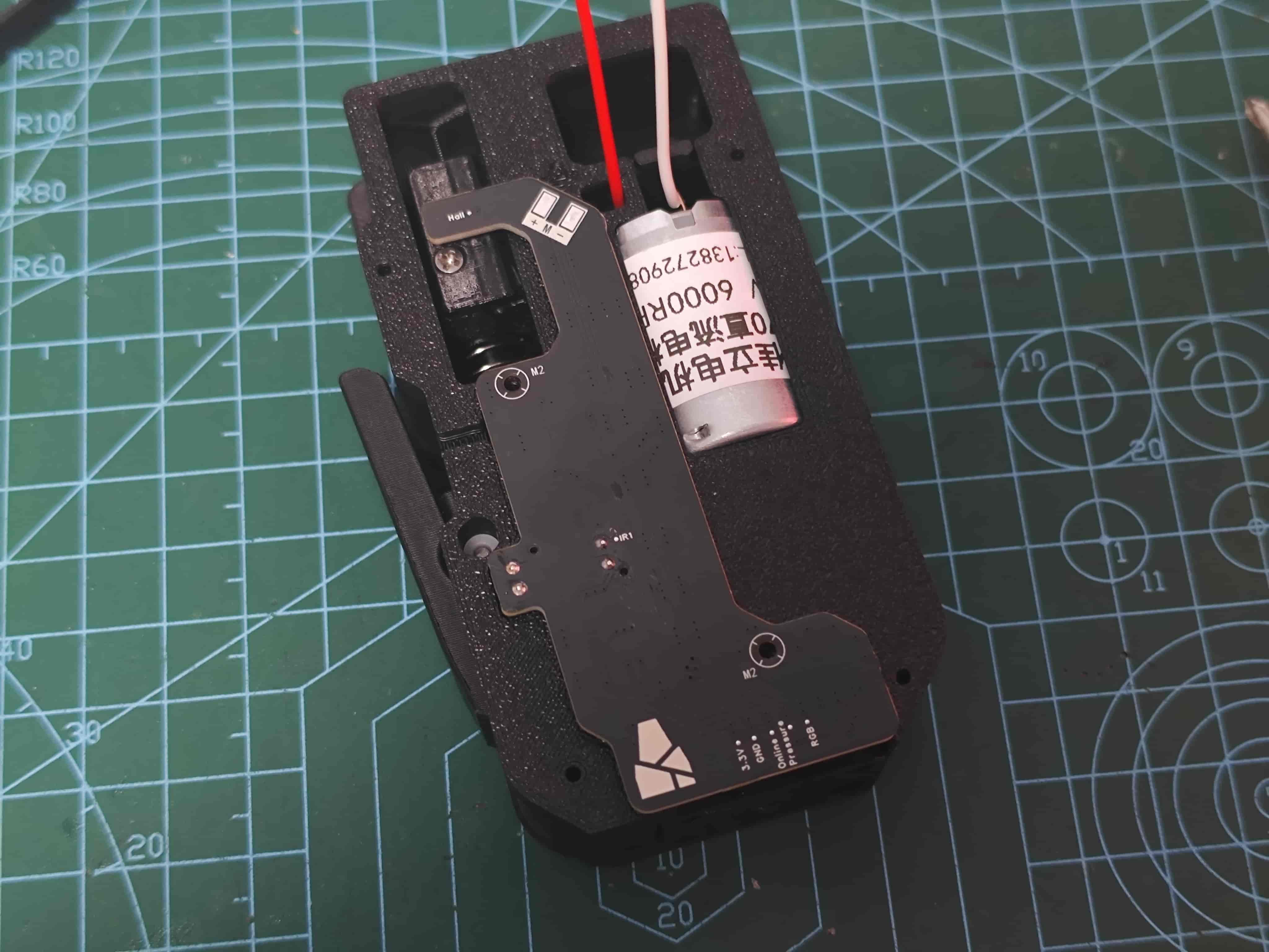
Secure with two M2*8 self-tapping screws, then solder the motor wires.
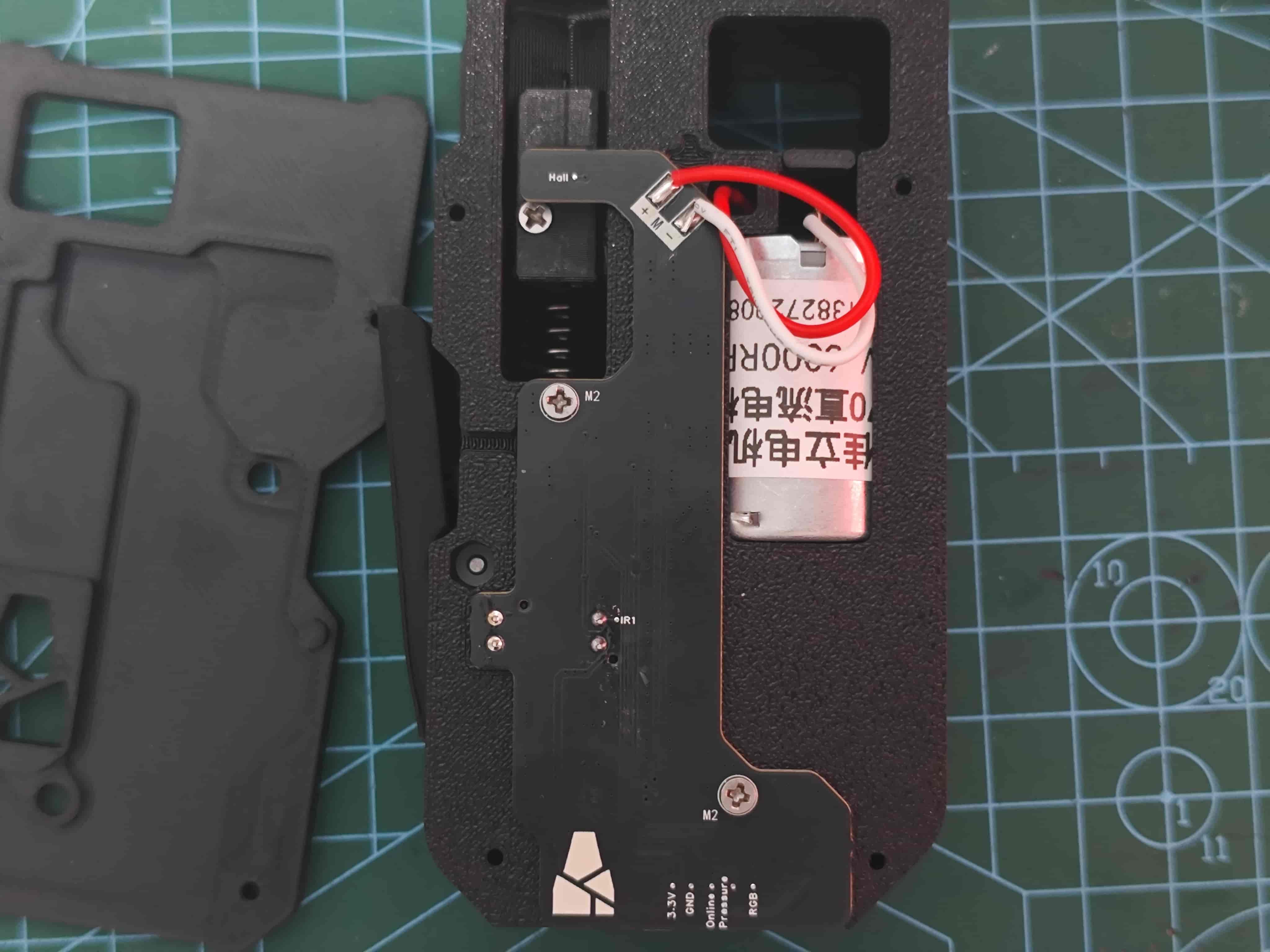
Tuck the excess wires into the slot.
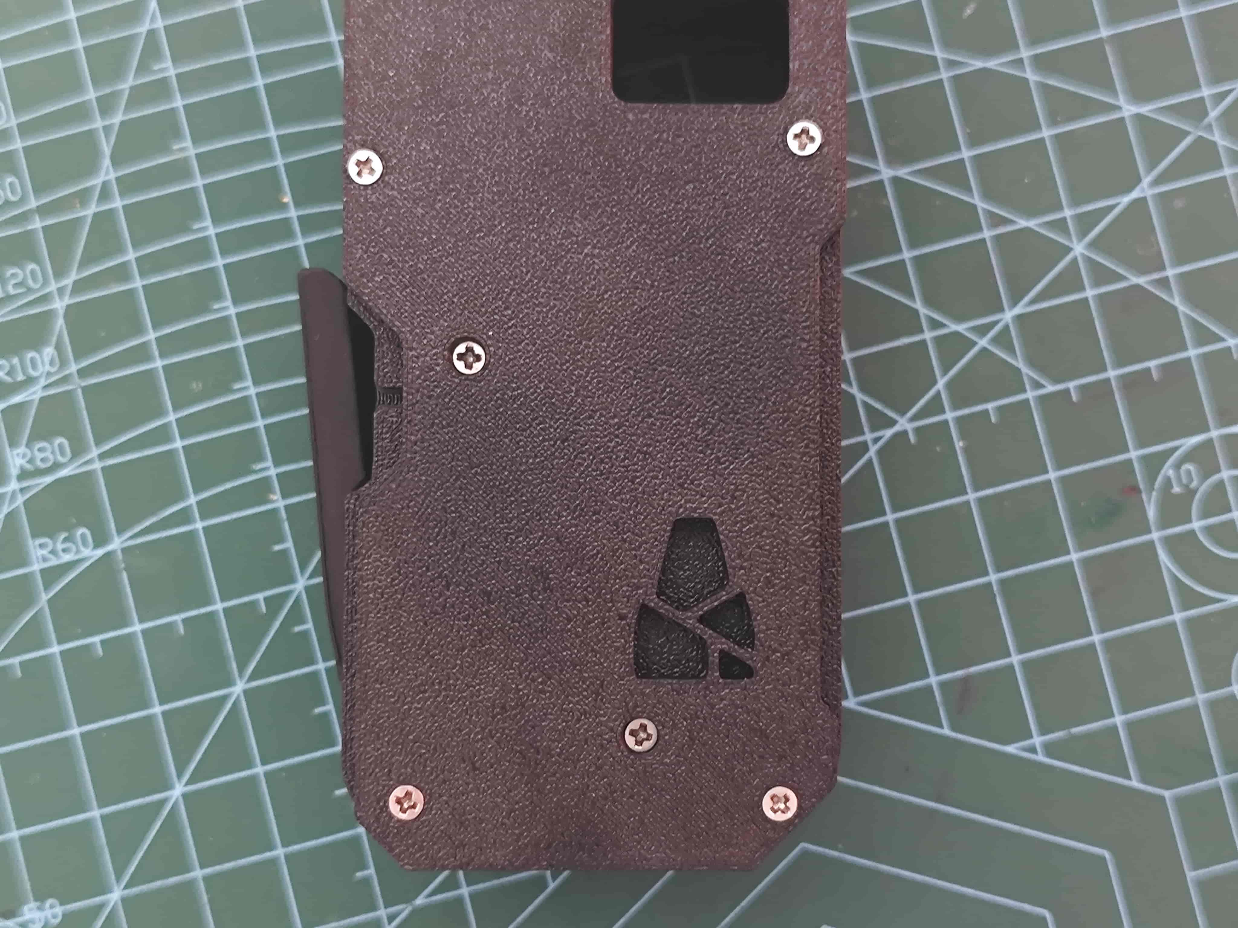
Install the Front Cover
Secure with four M2*8 self-tapping screws.
Install Pneumatic Connector
Screw the pneumatic connector into the slider.
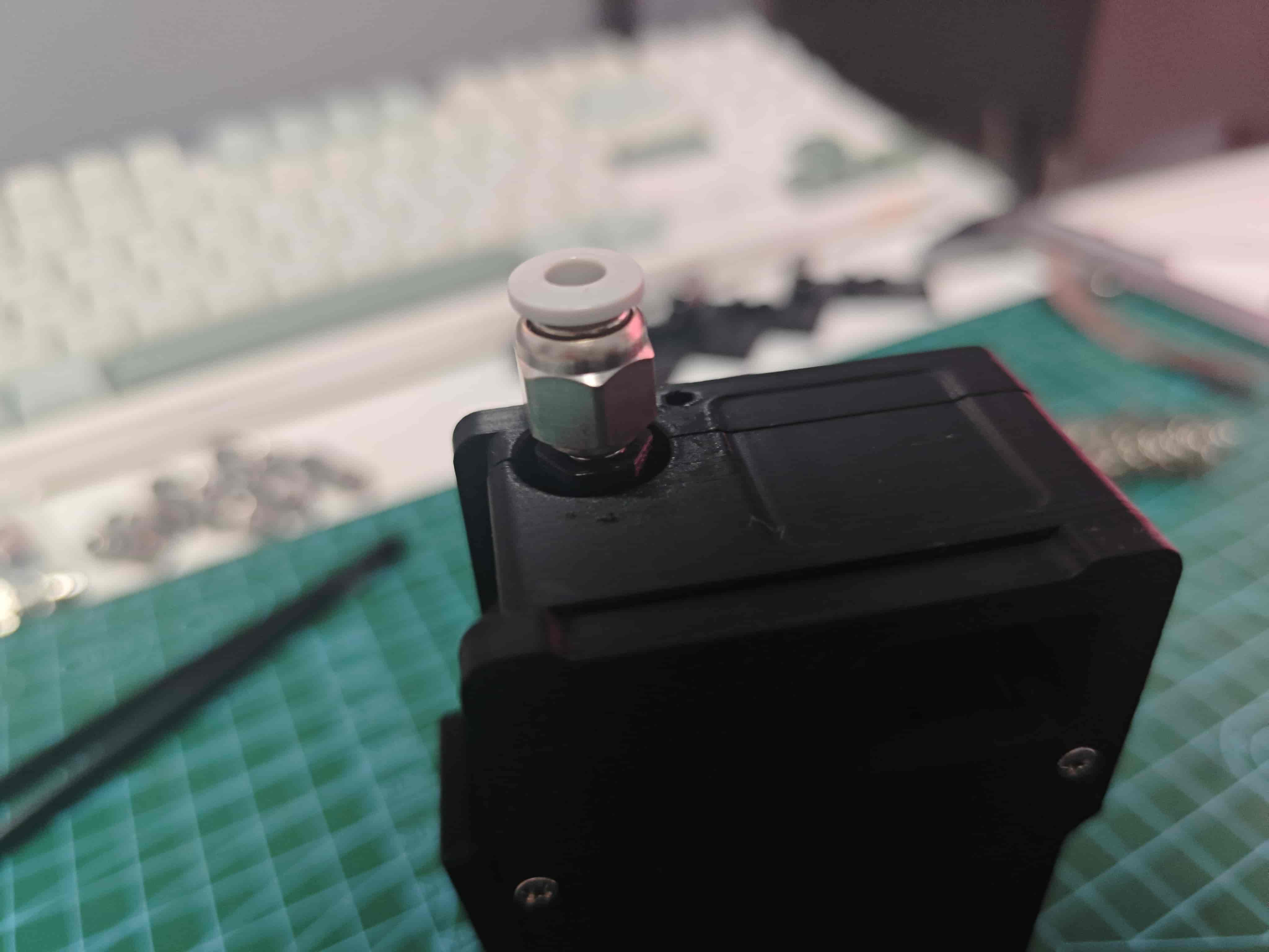
Done
You can now connect the board and perform basic filament loading/unloading tests 🎉
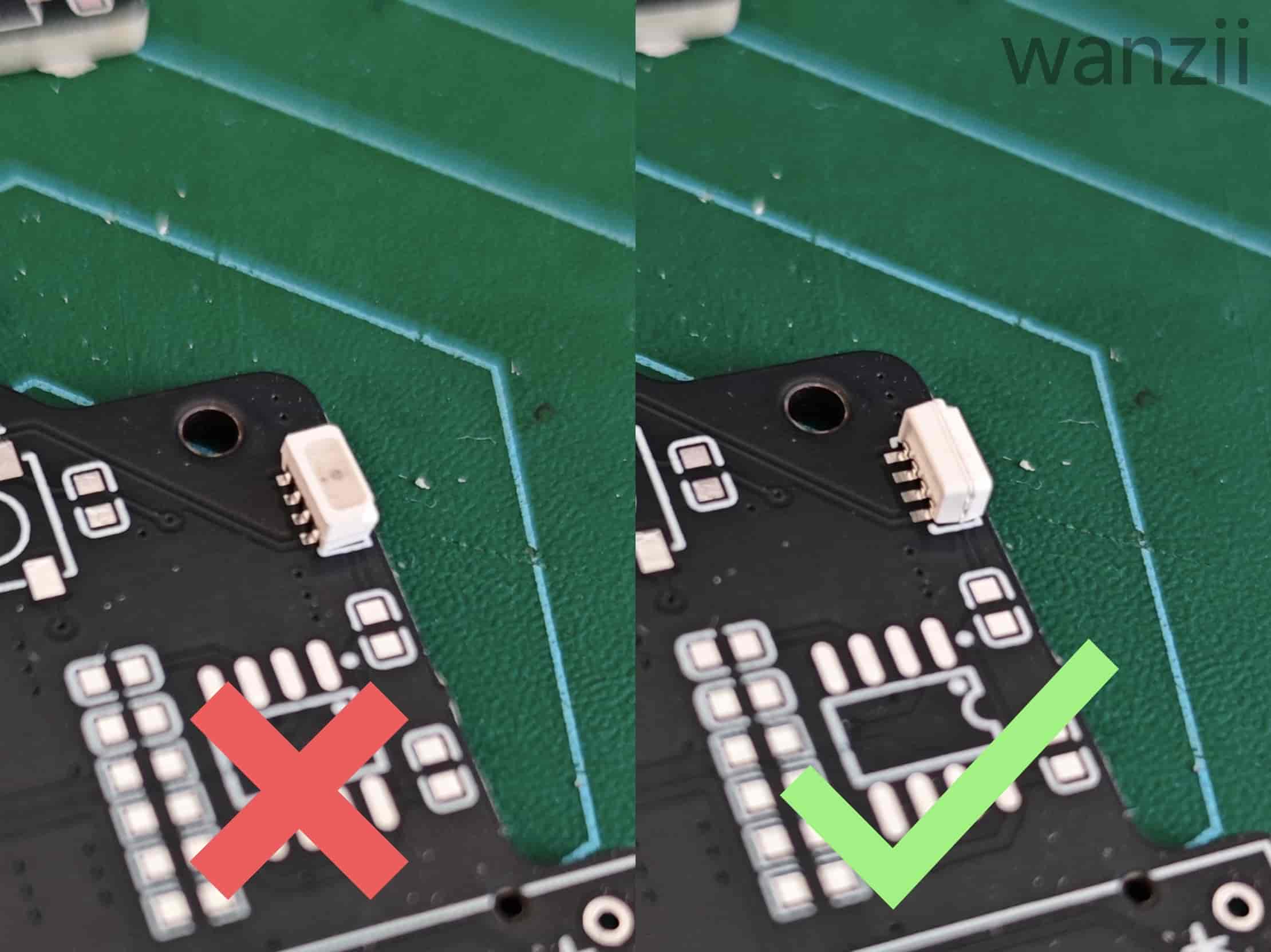
If your WS2812B (4020 size) LEDs do not light up under any condition, double-check the soldering direction.
LED Status Table
In the table below,
-indicates the LED is unaffected or its state is unknown.
| Condition | Side LED | Top LED (Fiber) | Troubleshooting |
|---|---|---|---|
| Radial magnet not installed | - | Red | Check radial magnet installation & AS5600 soldering |
| Normal operation | - | Blue | - |
| Channel selected (active) | - | White | - |
| No filament inserted | Black | - | - |
| Filament online | White | - | - |
| Buffer pressed (slider) | Blue | - | If side LED is red, reverse slider magnet polarity |
| Buffer released (slider) | Red | - | If side LED is blue, reverse slider magnet polarity |
Mainboard: Blue indicates normal communication with the printer; Red indicates abnormal; any other color is abnormal 🔧