

370 Motor Version x BMCU-Stardust Microswitch Modified Version Assembly Tutorial
Note
This version is a modified version by the group member @Stardust, and the content is also from this group member.
Introduction
- This tutorial is the assembly guide for the
370 Version X BMCU-Microswitch Modified Version, which has high compatibility with the original version but is not the original BMCU370 version. - This means you can use it as a reference for the original 370 version (non-inverted steel ball version).
- Project open-source address: BMCUx - Oshwhub.com
- Project model address: Makerworld CN Makerworld Global
- For the P1 series, you need to make some changes, such as the built-in five-way connector, which is still under improvement and will be updated once completed.
- Welcome to try the test firmware (currently being organized). The recommended version is
BMCU Test Firmware 2-6.bin. - You can customize and test the firmware here: bmcu370x github.com
- The model for this project is modified from the BMCU2.5 version shell.
PCB BOM
PCB Notes
If you encounter issues, please first check the left sidebar - [FAQ].
Mainboard Soldering Section
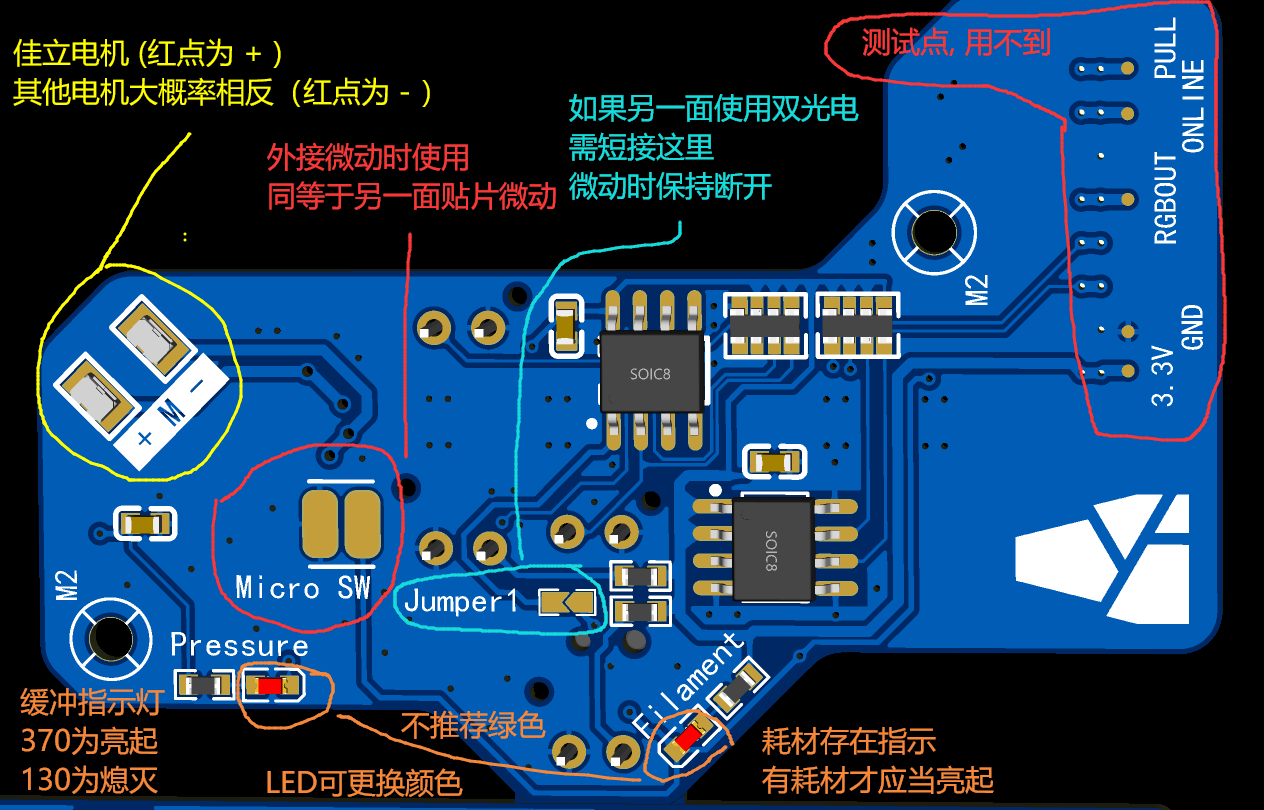
- Pay attention to the diode direction.
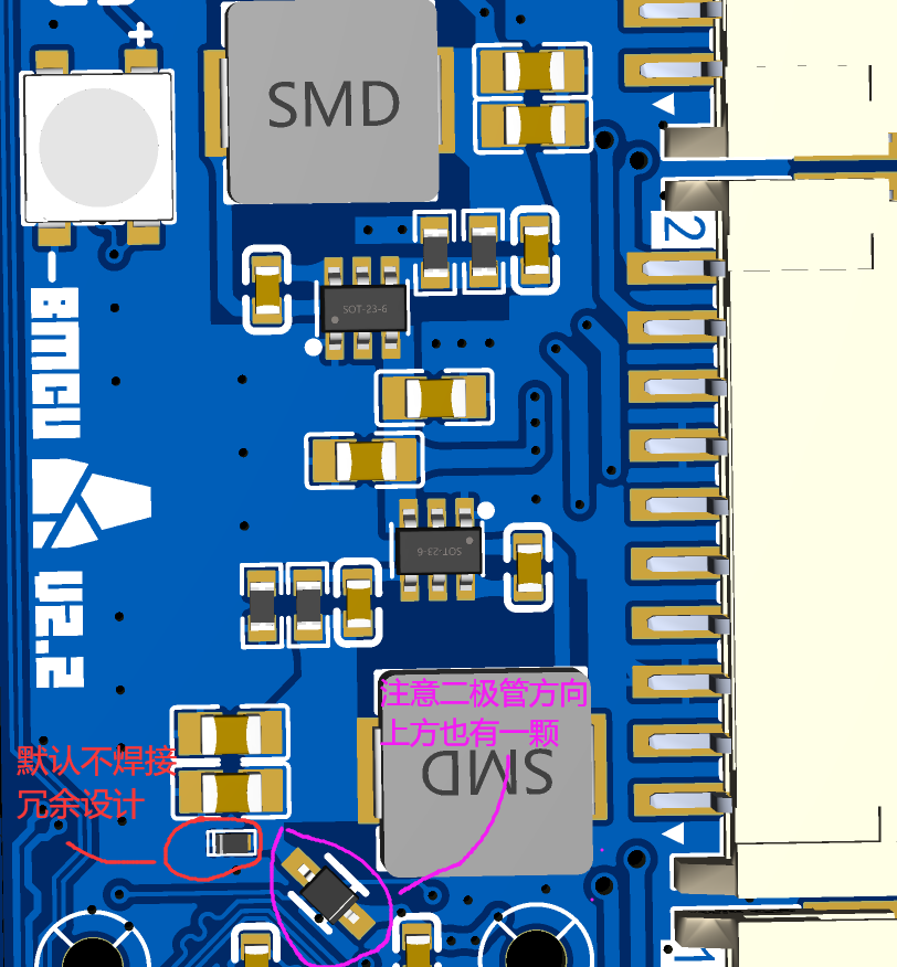
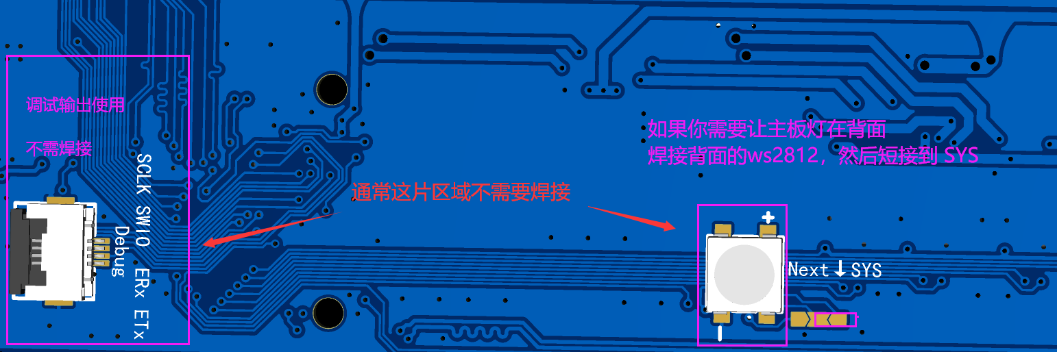
- Solder the backside as needed.
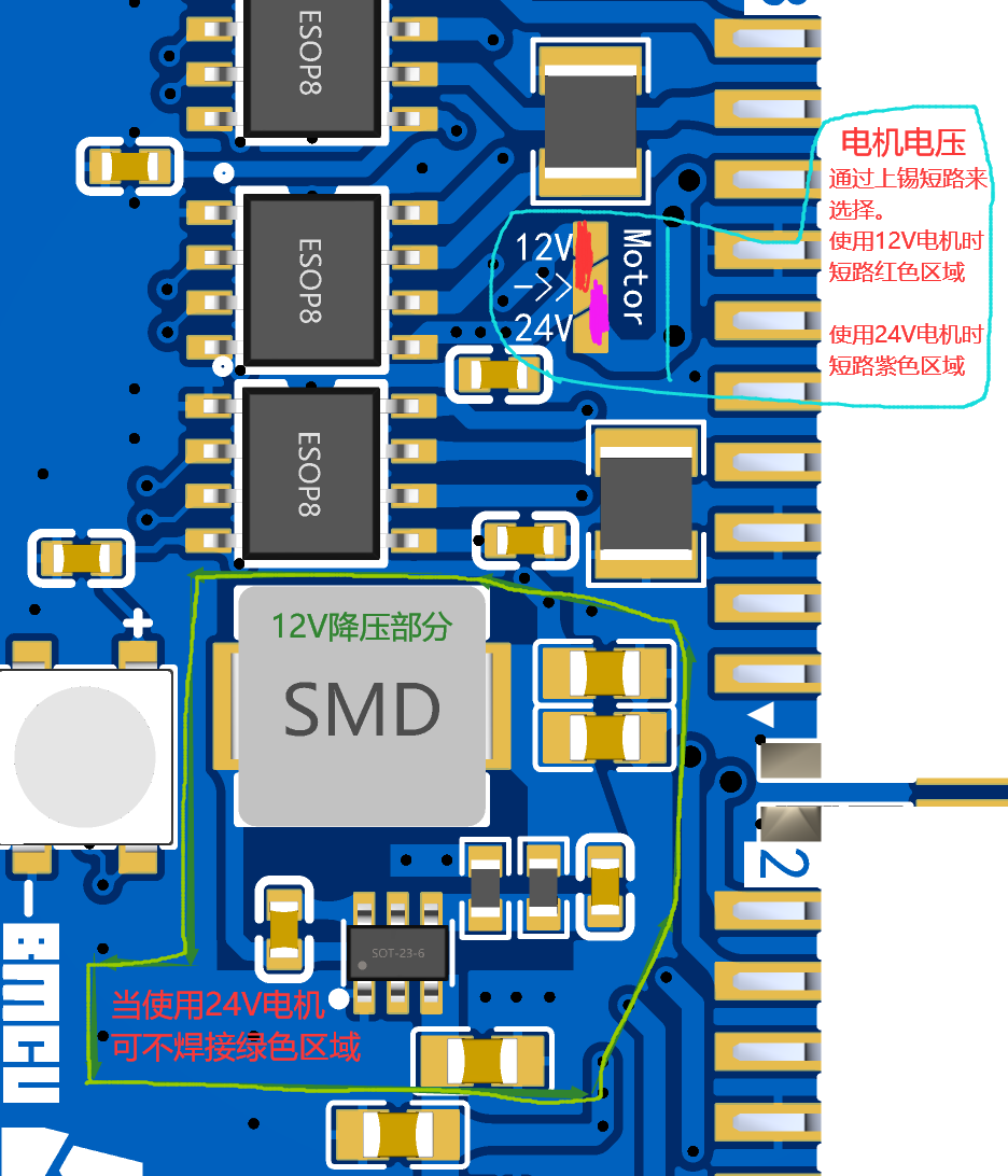
- Motor voltage selection and soldering.
- Slave section: Revert to dual photoelectric (130 basic version).
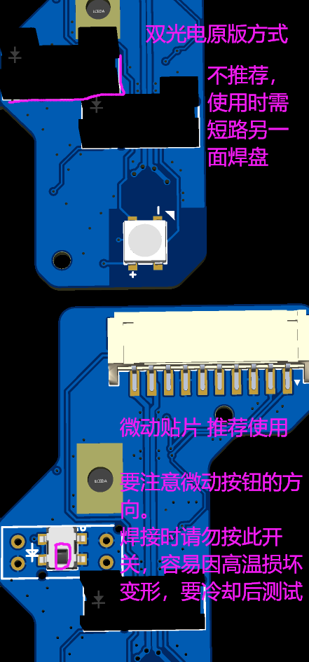
- Slave section - Functions.
Component Assembly
- The tutorial may have oversights. If you find any errors, feel free to correct them and discuss with group members.
- The shell is based on the first version for photography, so the appearance may slightly differ.
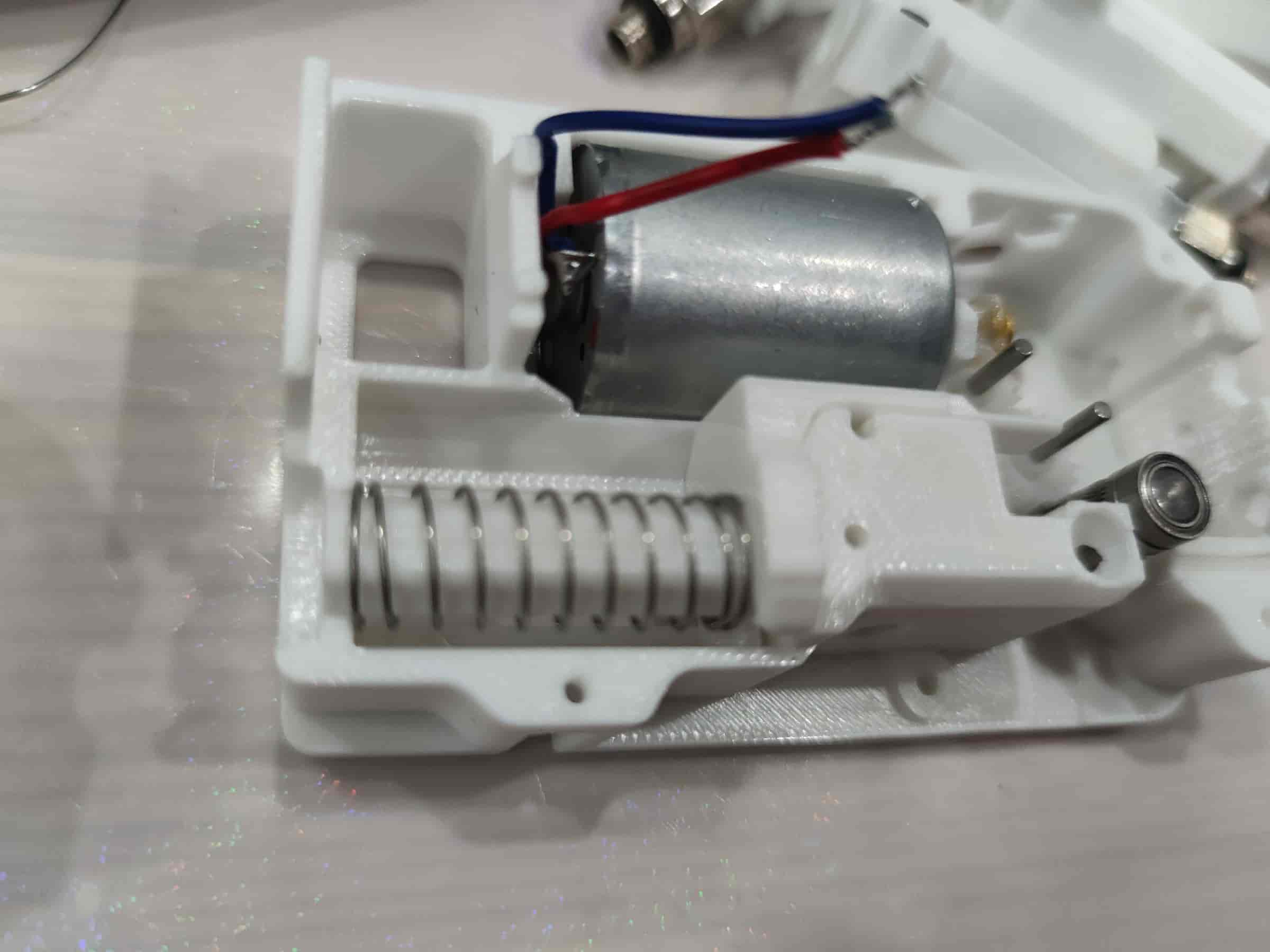
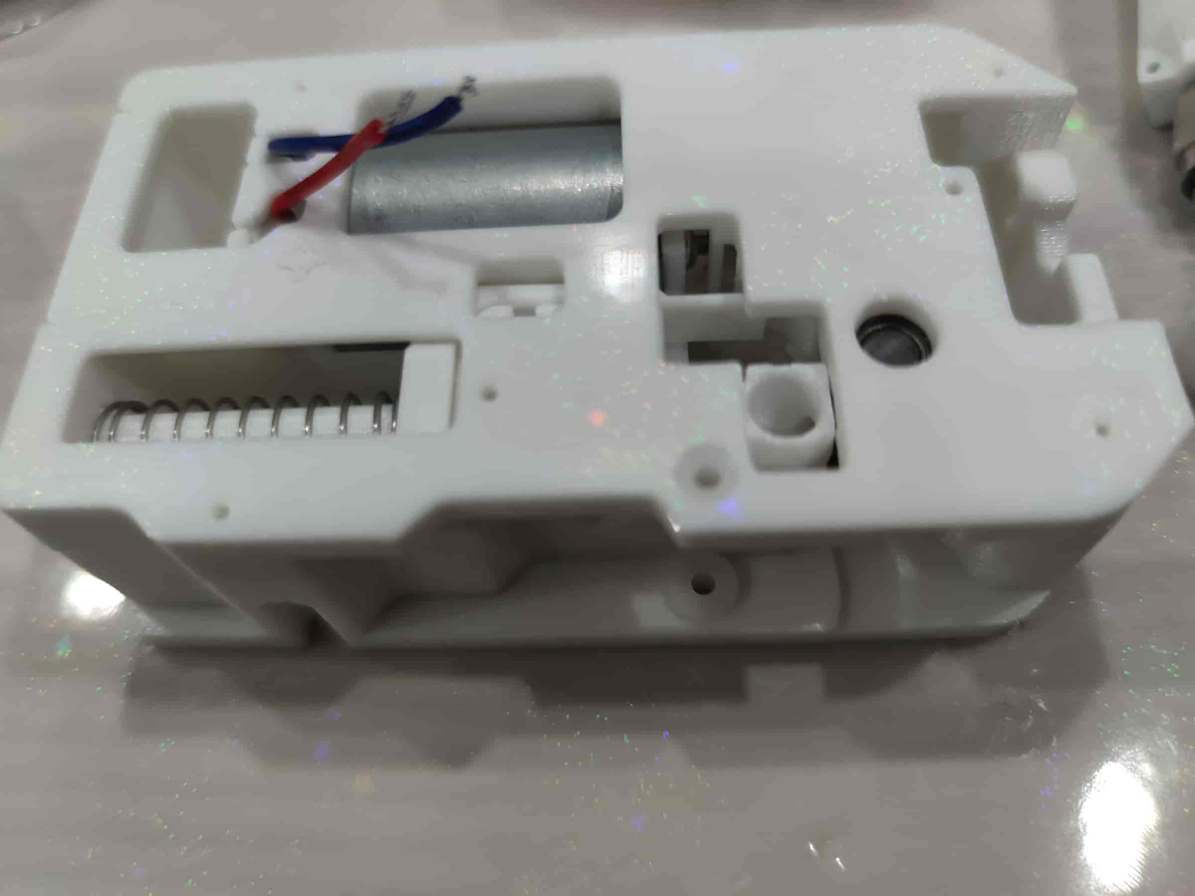
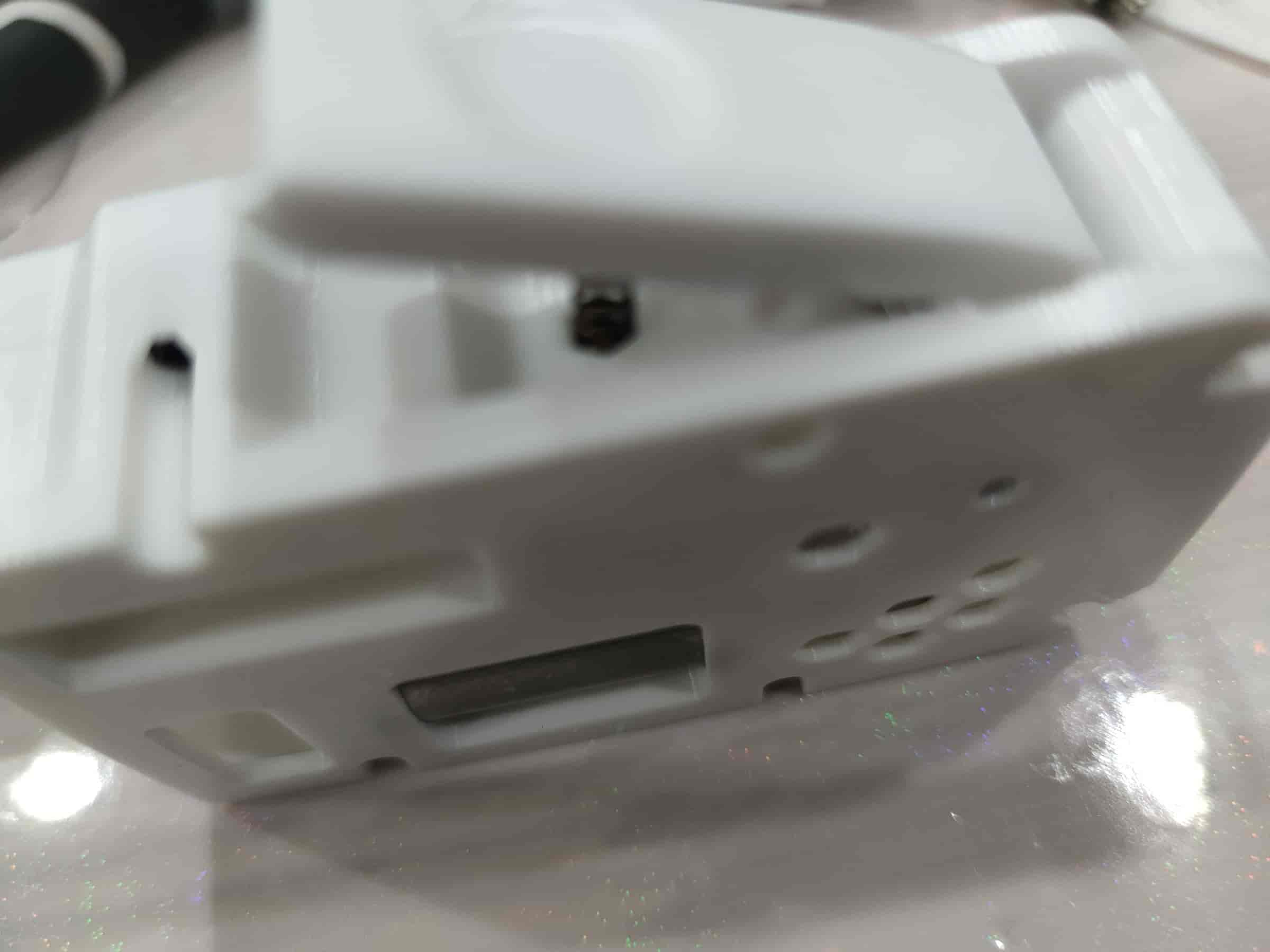
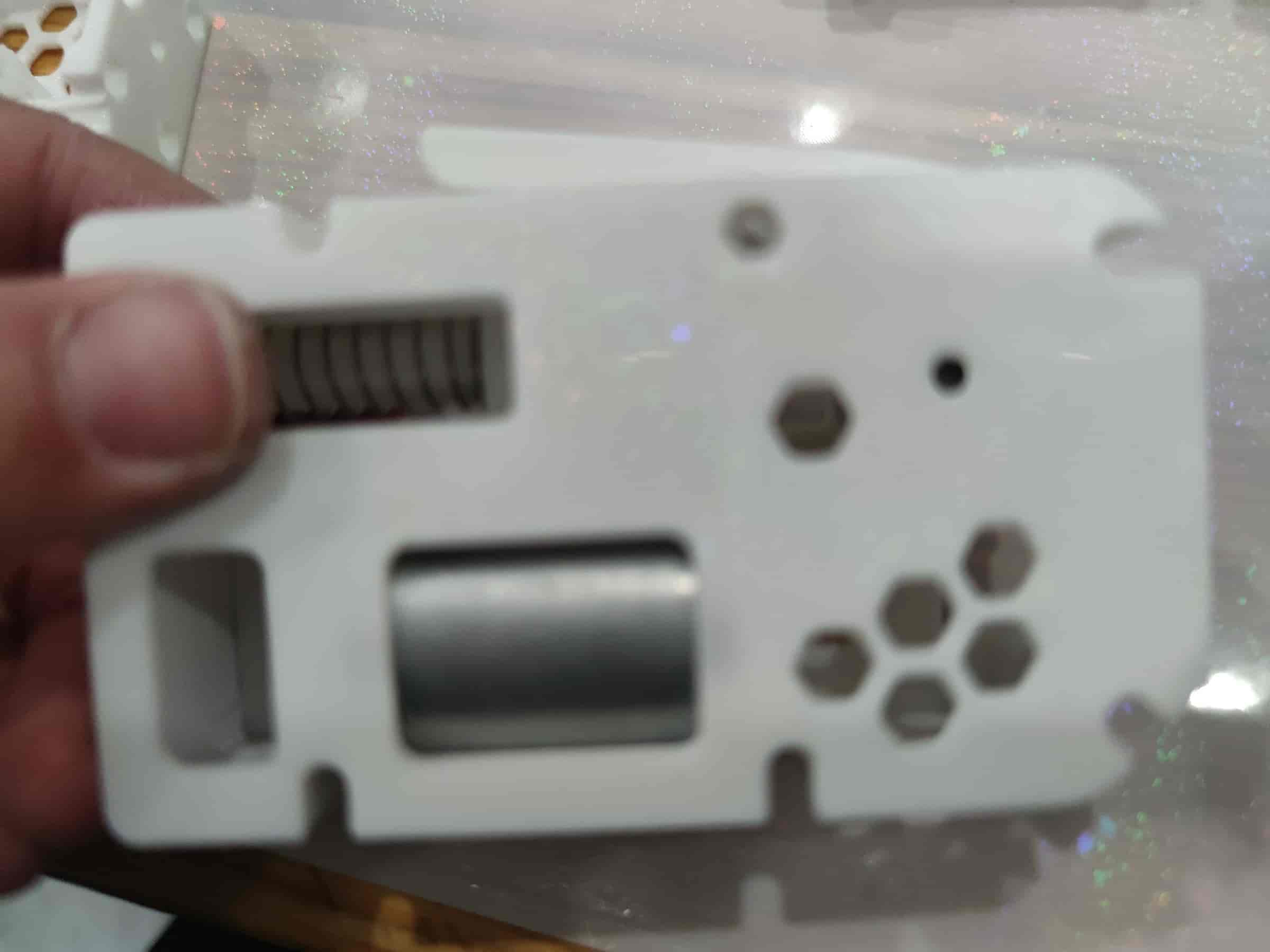
- First, assemble the bottom shell part.
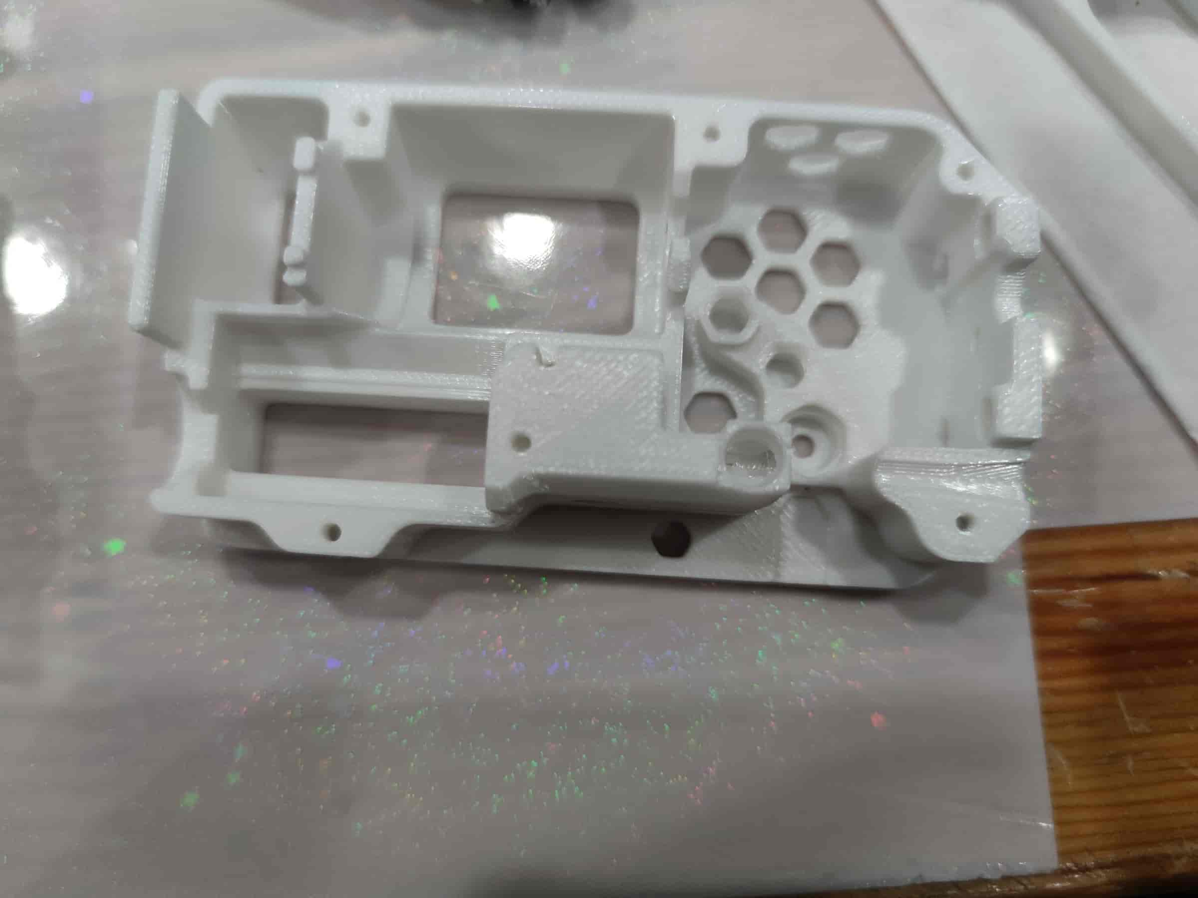
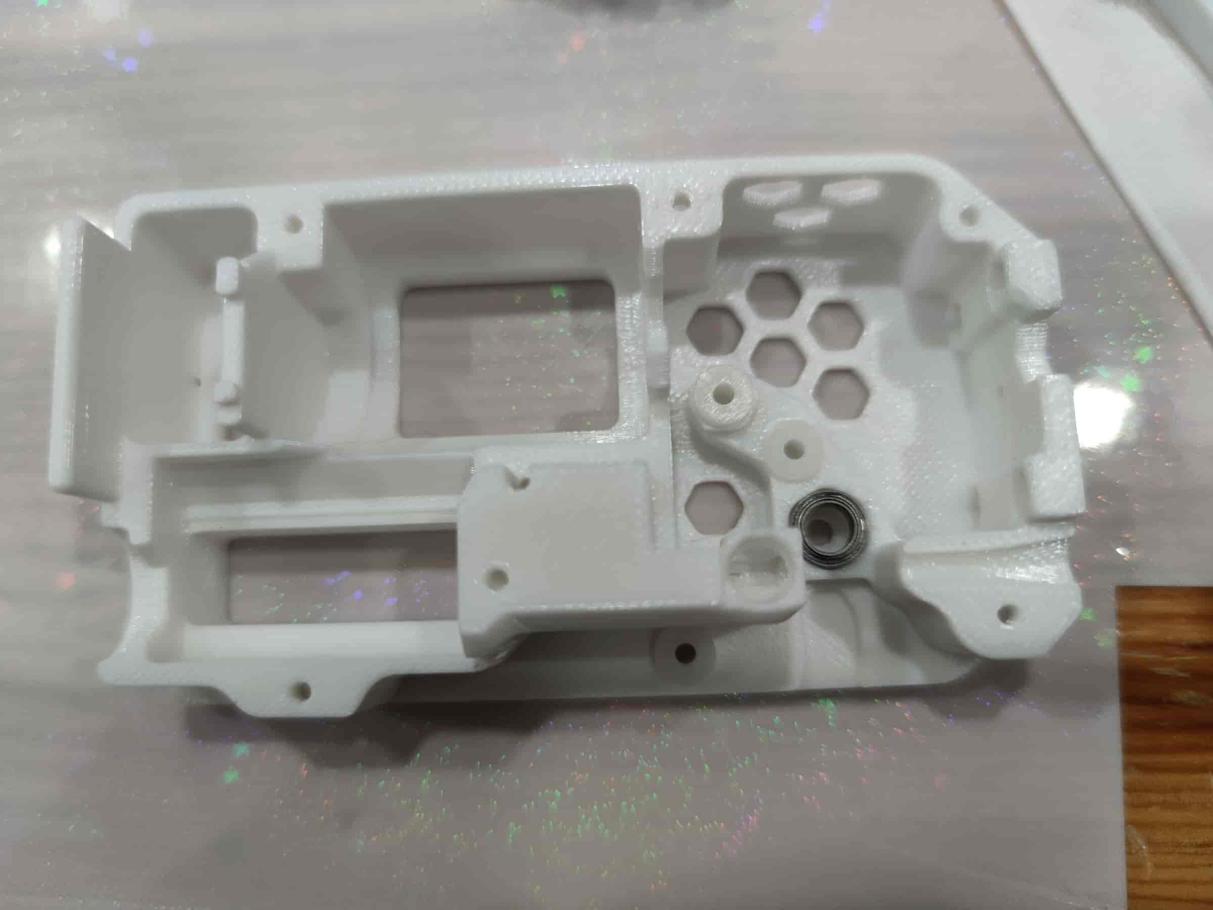
- Install 3 bushings and 1 MR85ZZ bearing. Ensure the bushings are pressed tightly for optimal performance.
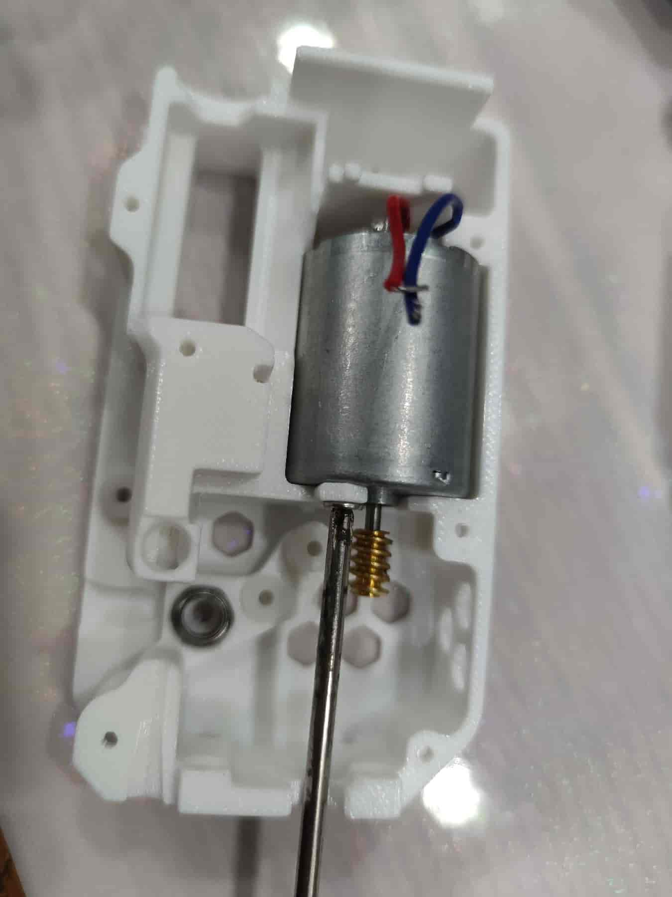
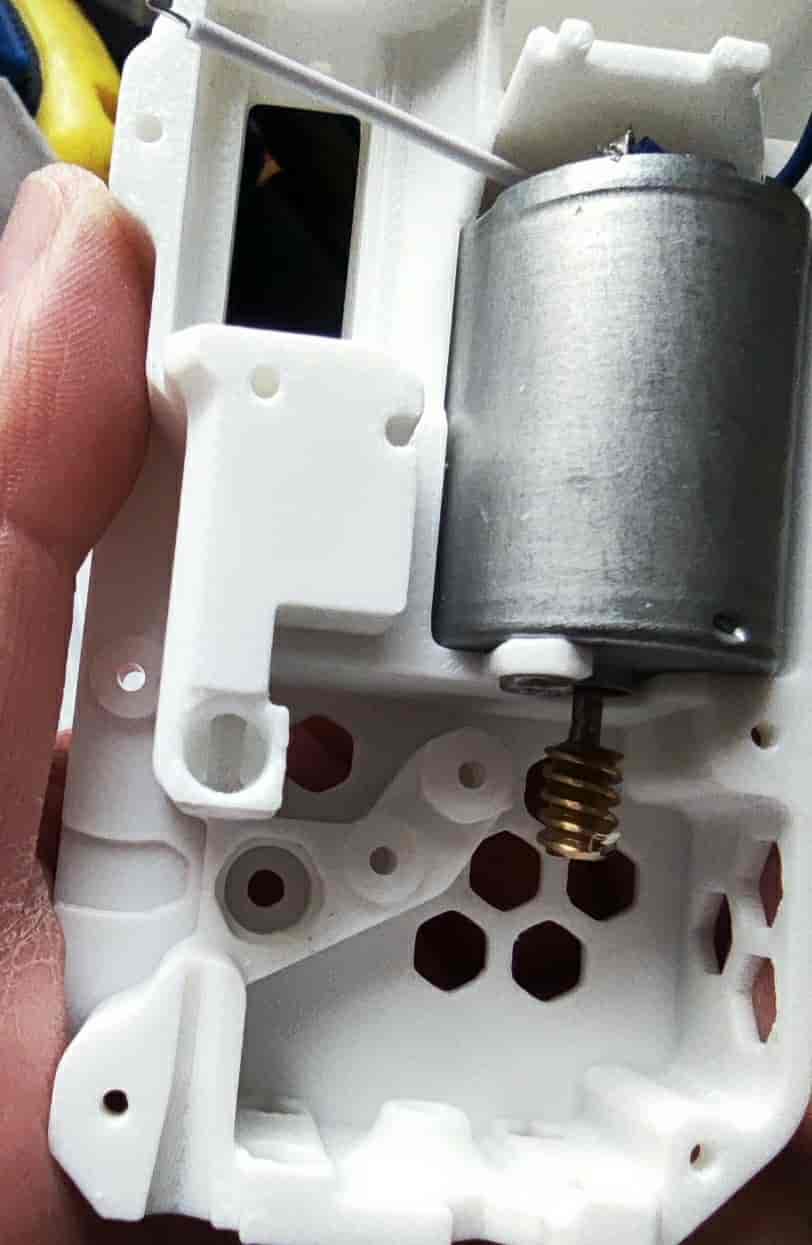
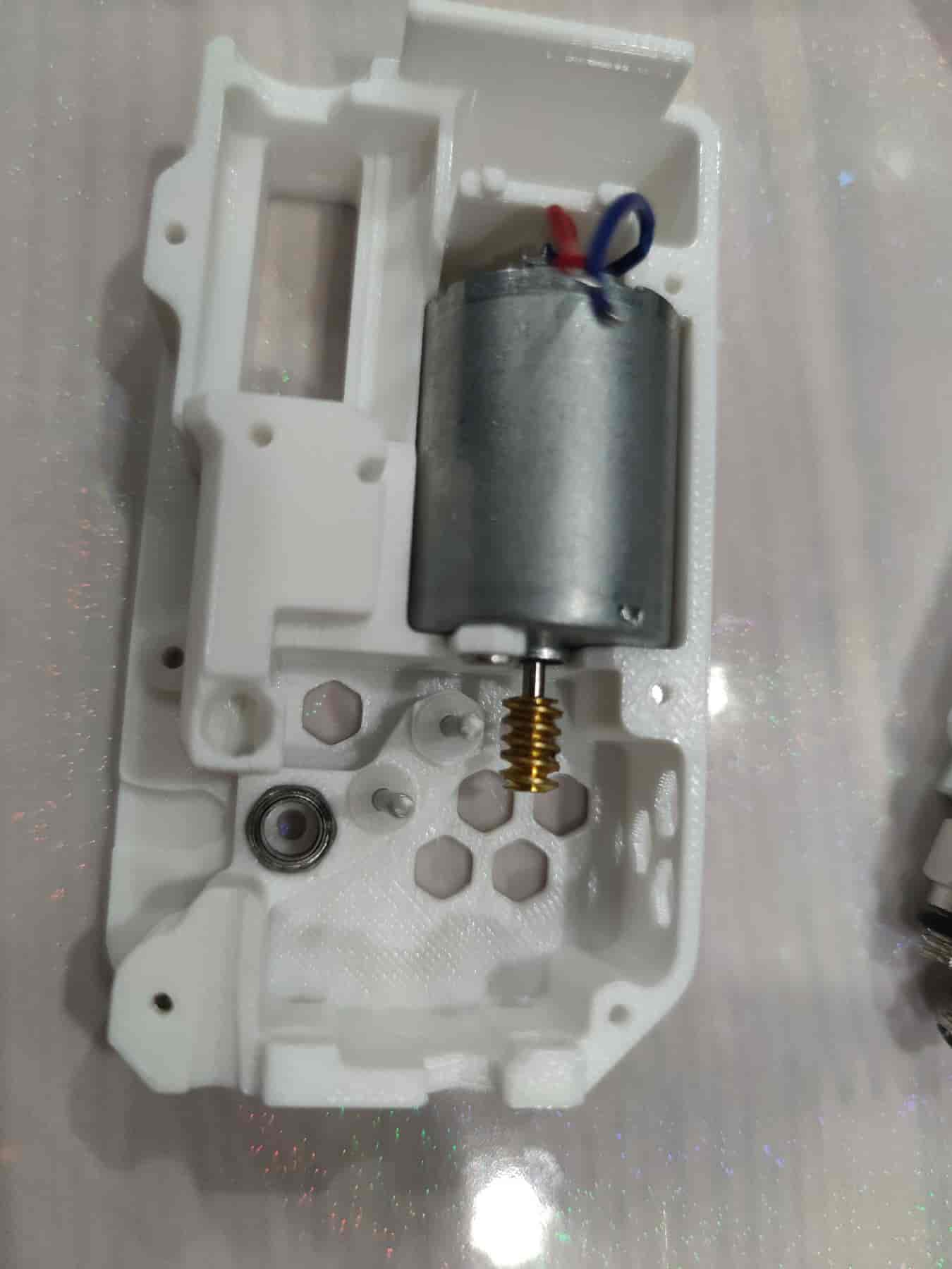
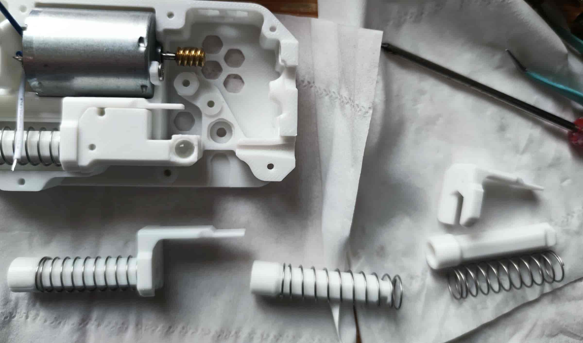
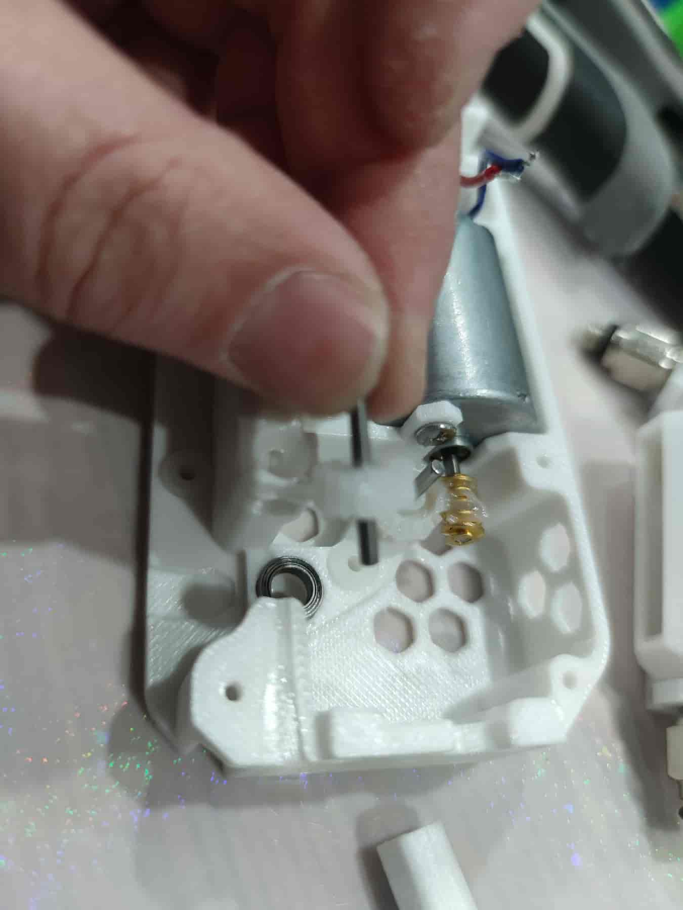
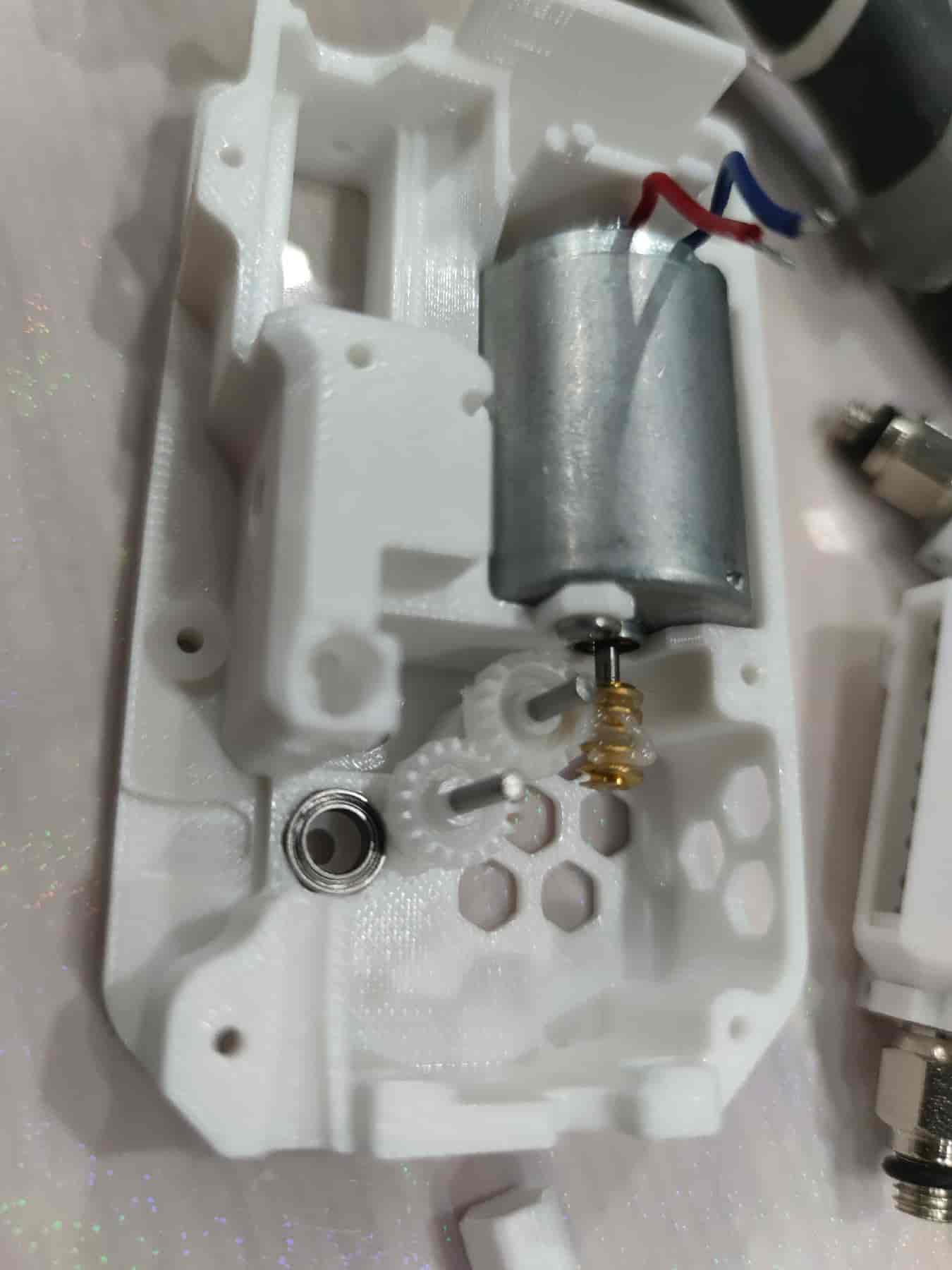
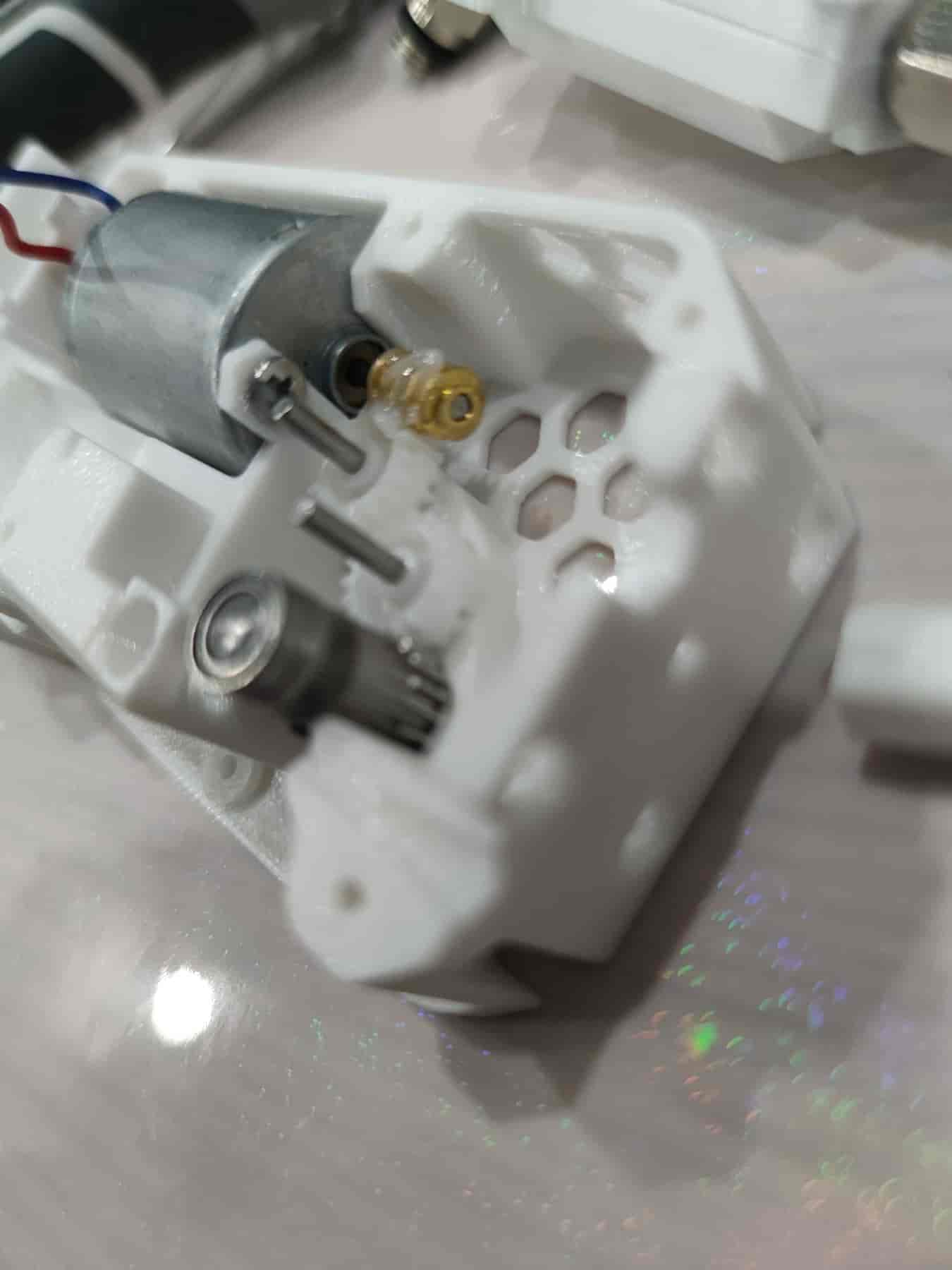
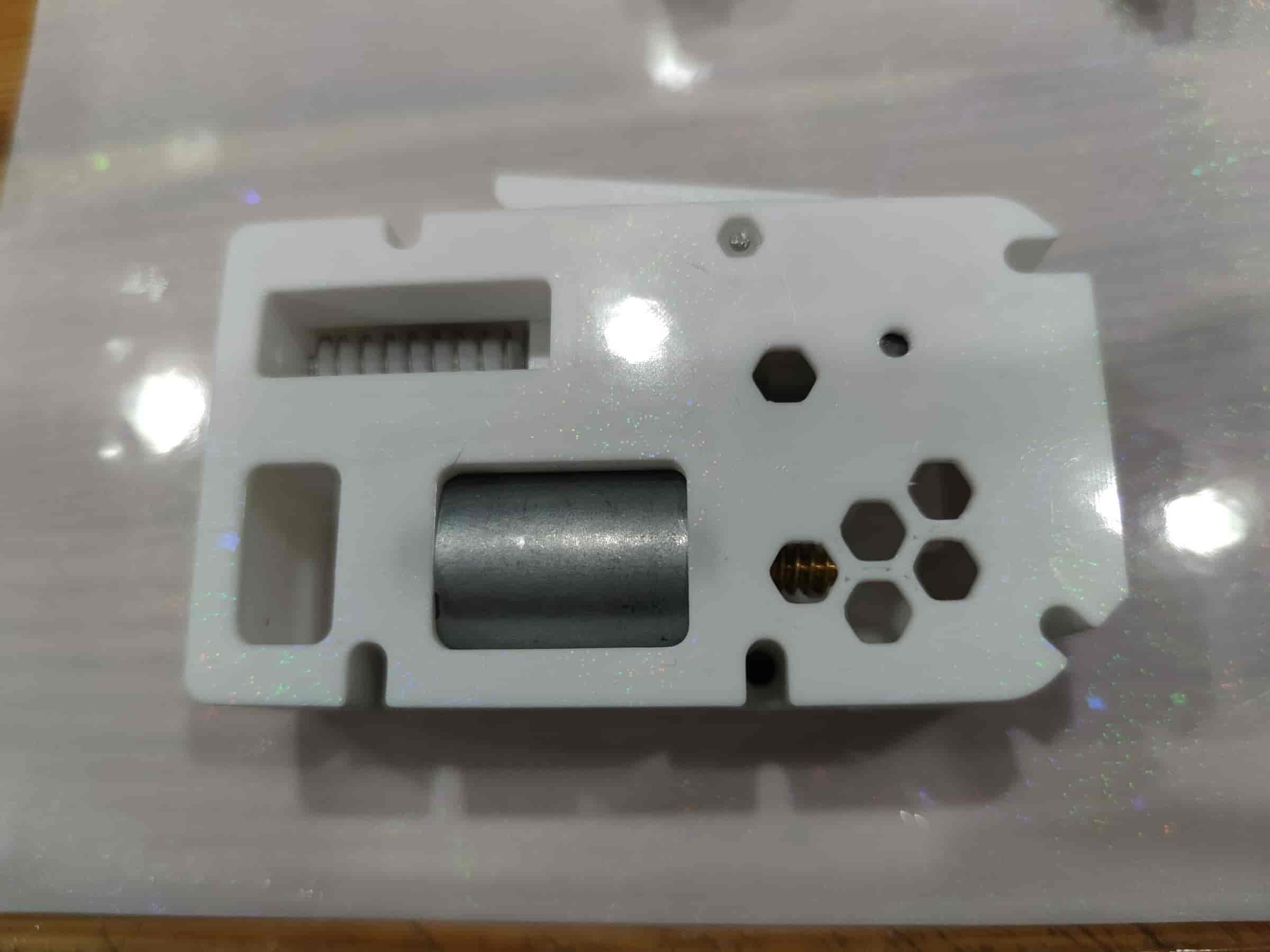
- Ensure the motor wires are soldered. If the motor lacks a worm gear, insert a plastic worm gear and align it with the motor shaft. Then place it into the bottom shell, align the screw holes, and secure it with M3x5 flat-head screws.
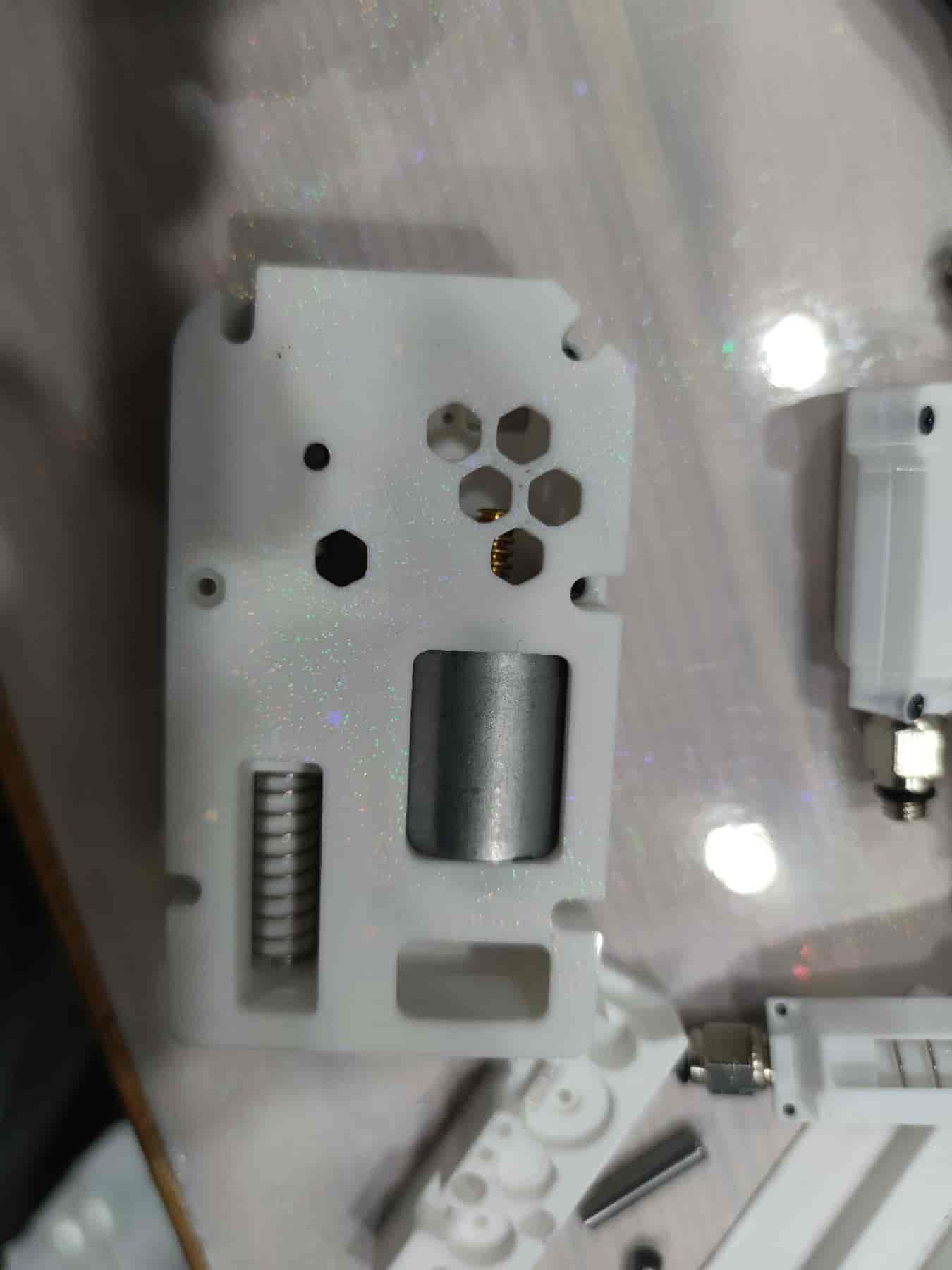
- Ensure the glass bead area is smooth. If there are small protrusions, use a craft knife to trim them.
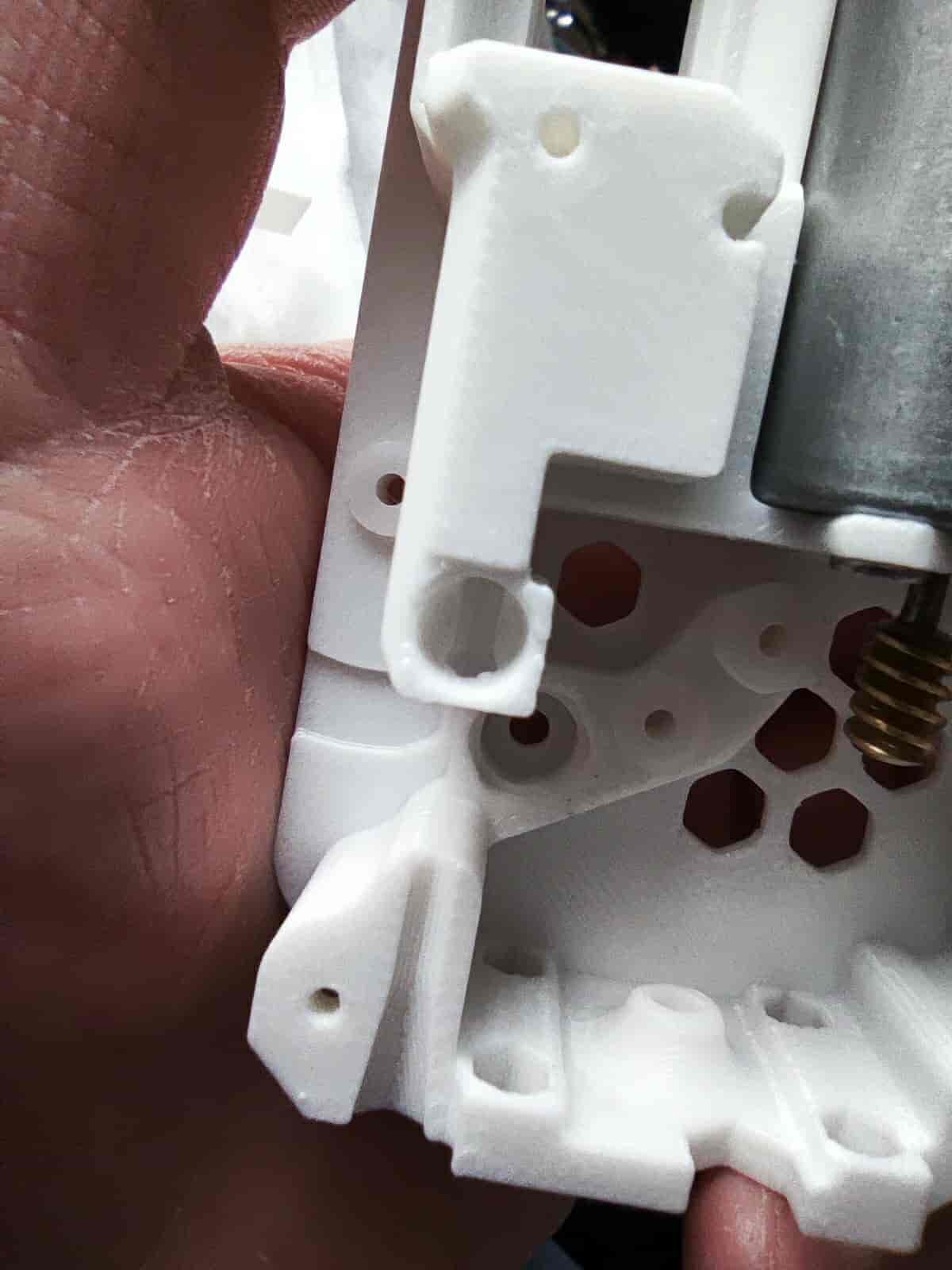
- After trimming, proceed to the next step.
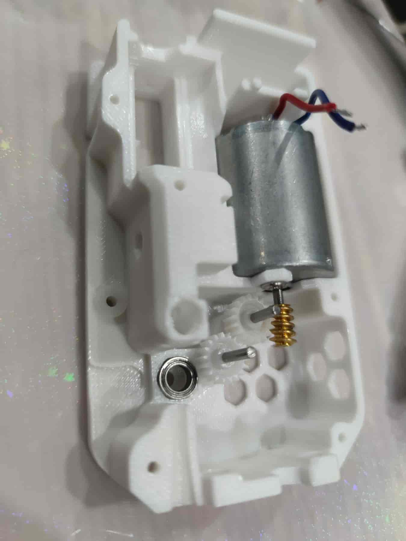
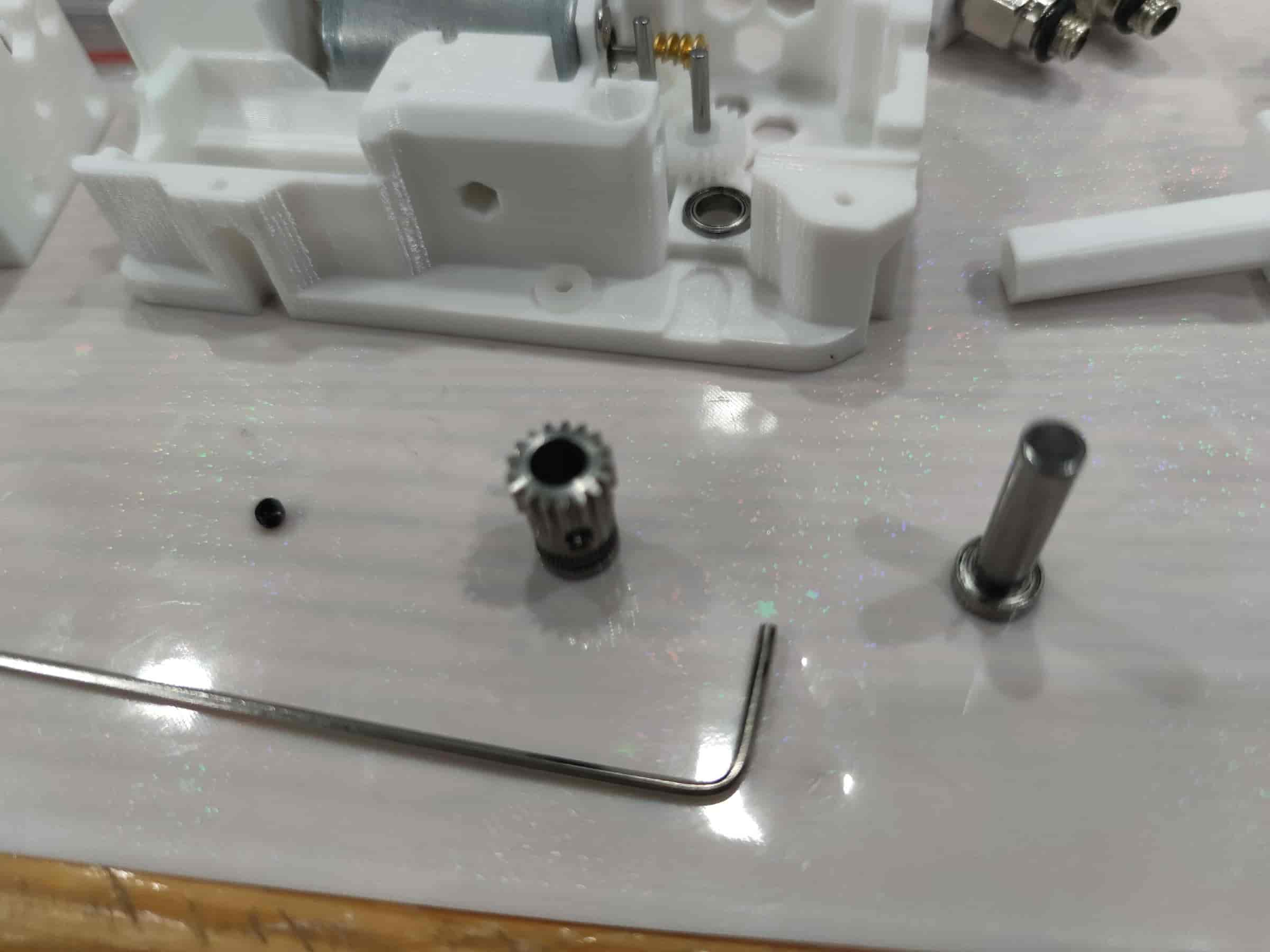
- Insert two M2x20 dowel pins. For metal gears, use pins with a diameter of 1.95/1.9mm. Note that the bottom shell/middle frame may need modifications due to the different thickness of metal gears. Metal gears are not recommended.
- Slide the 182A plastic gear onto the dowel pin and press it down firmly. Pay attention to the angle and force. It's recommended to press the gear closer to the motor first. For metal gears, simply place them on.
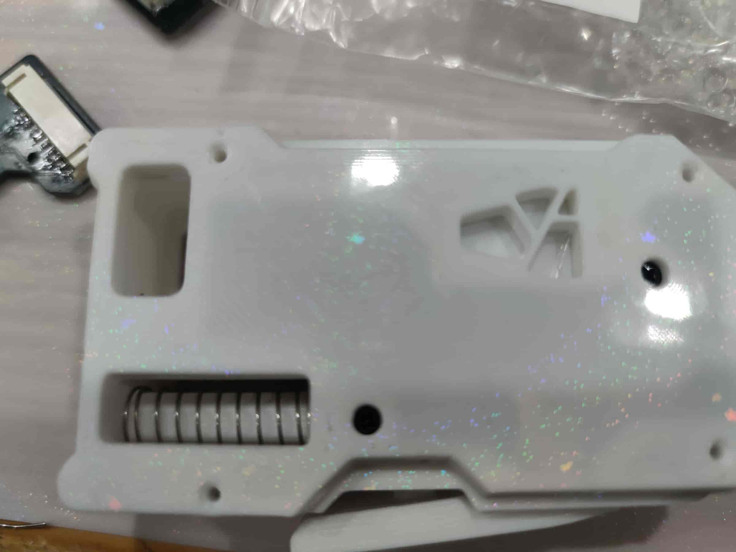
- Take out the buffer cylinder printed part and the slider, then snap them together. Ensure the filament can pass through the cylinder with almost no resistance. Otherwise, adjust the hole compensation and reprint the cylinder.
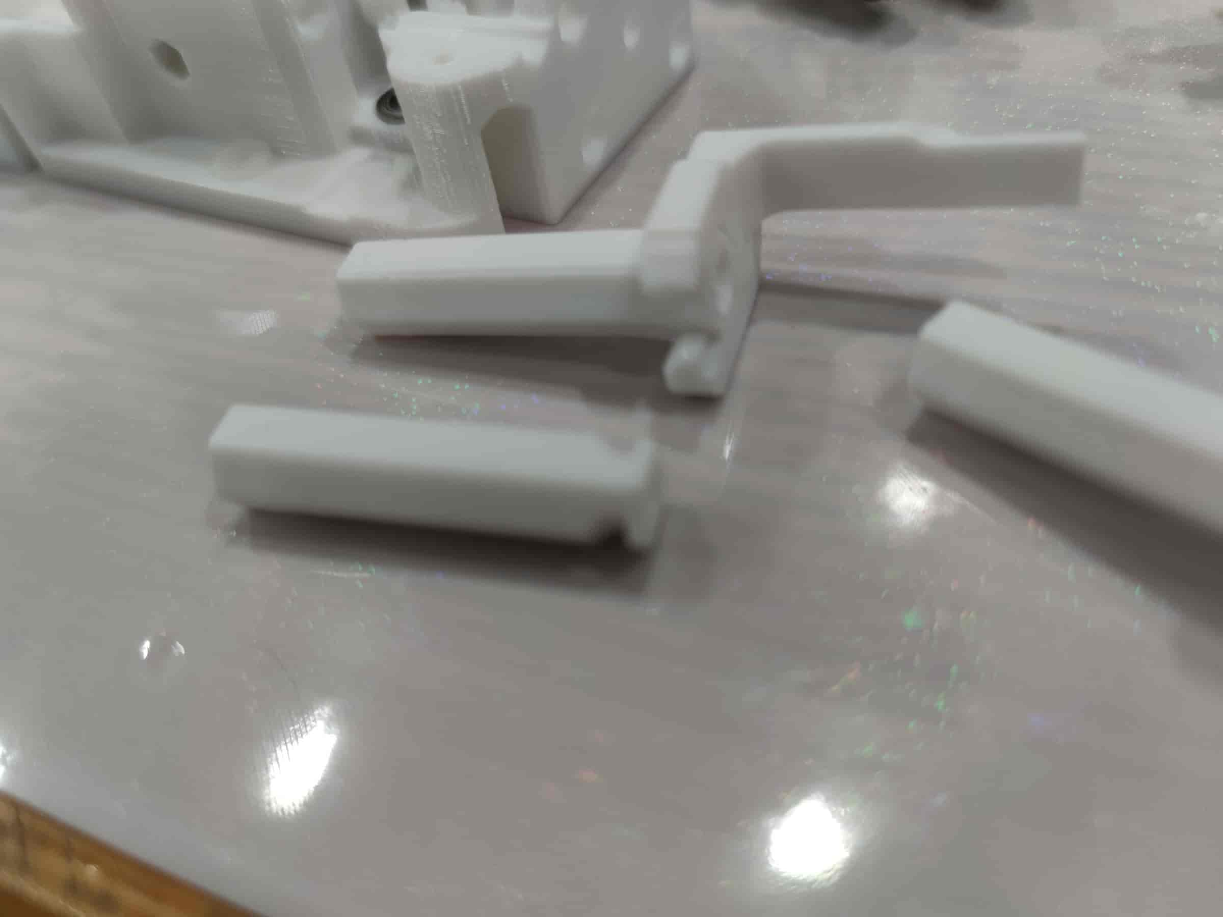
- For the new buffer cylinder, you may need to insert the spring (10mm diameter spring) first.
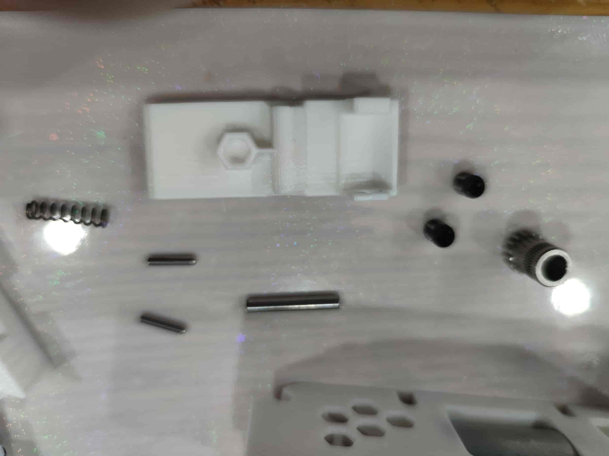
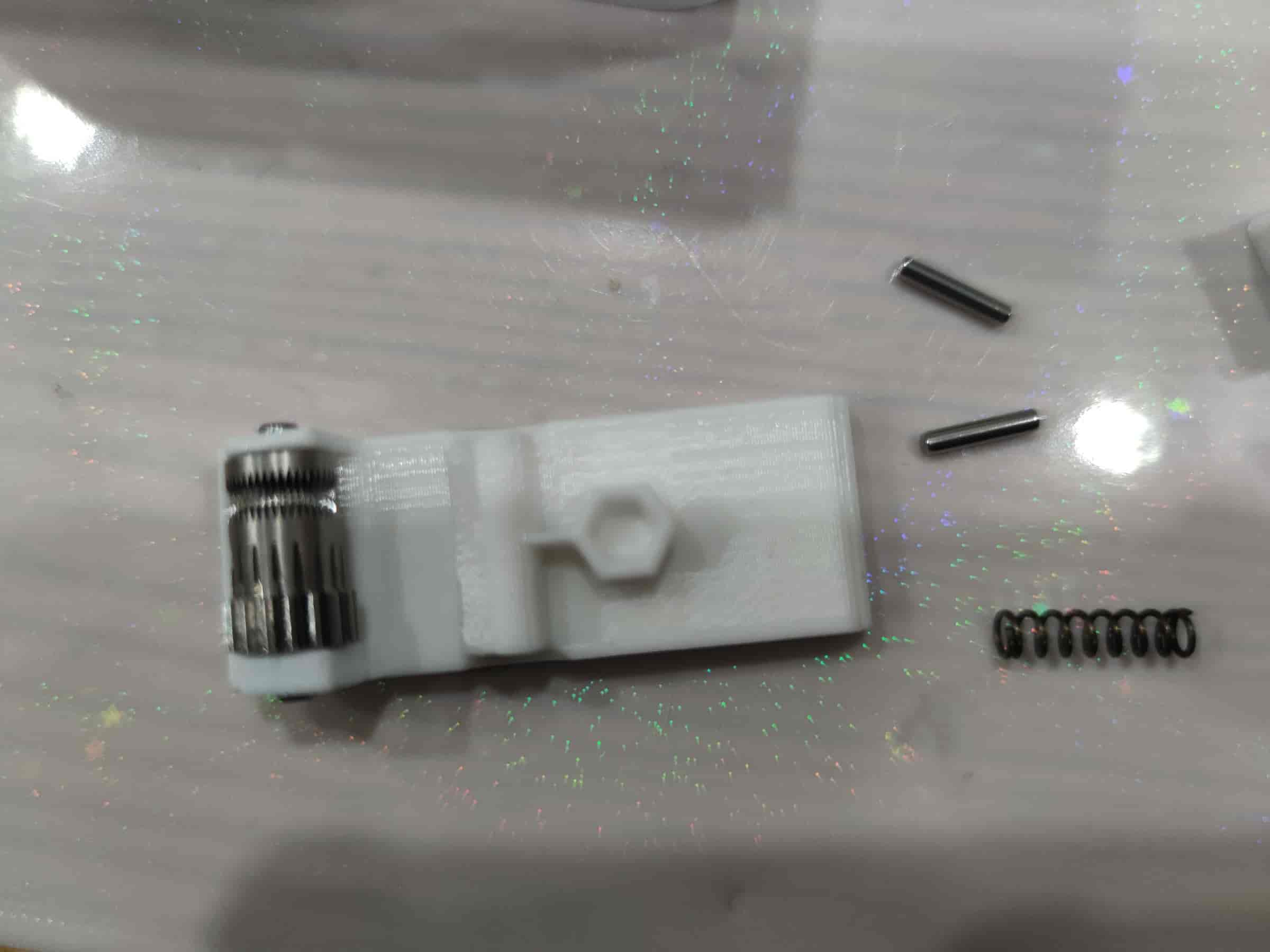
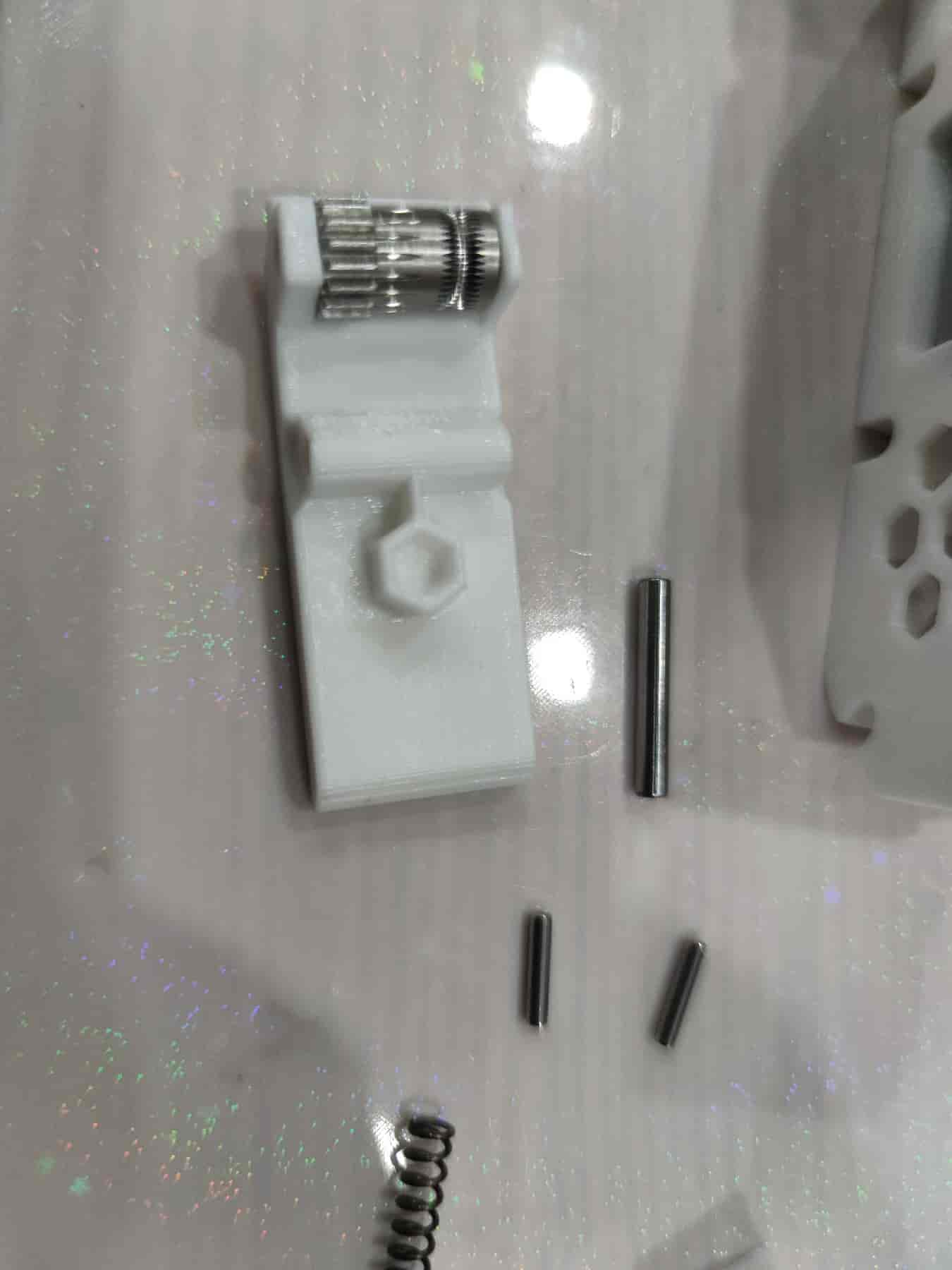
- Take out the BMG extruder gear with holes, a black set screw, an MR85ZZ bearing, and multiple M5x22 dowel pins. Due to tolerances, test-fit the MR85ZZ bearing with the M5x22 dowel pin to find the one that fits snugly but can still be inserted easily.
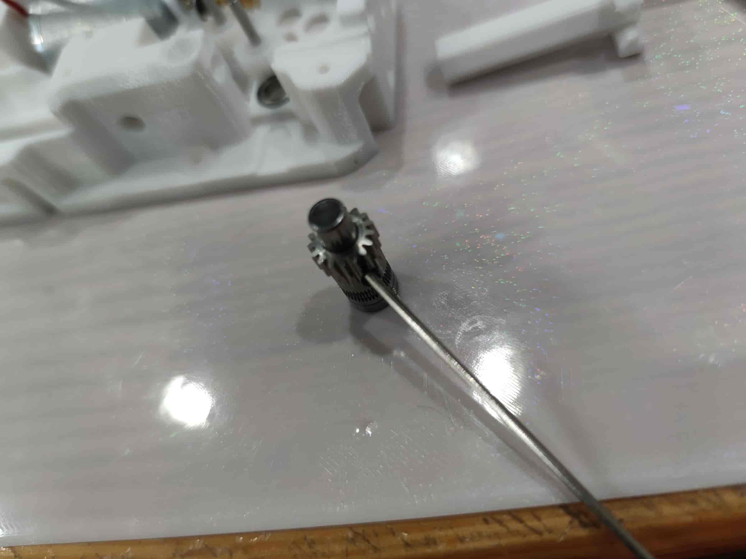
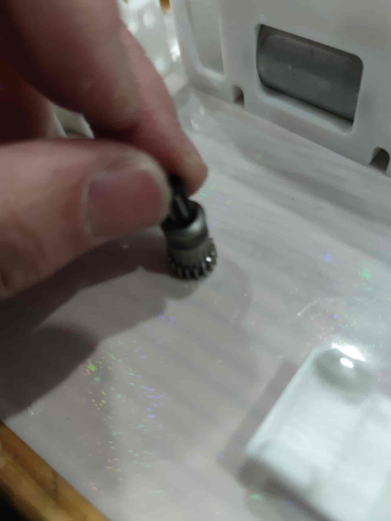
- First, place the MR85ZZ bearing. Insert the selected M5x22 dowel pin, then slide the BMG gear (toothless side down) onto it. As shown below, ensure everything is pressed down to form a flat surface. Use a hex key to tighten the set screw, ensuring the BMG gear can rotate the bearing via the dowel pin.
- Take out the gears and lubricate the motor worm gear and 182A gear. Then reinstall them, but avoid lubricating the BMG gear to prevent grease from contaminating the filament.
- Ensure everything is properly installed.
- Then place the BMG gear, ensuring the upper part does not touch the lubricant. The lower part of the BMG gear may get slightly lubricated by the gears, but do not actively lubricate the BMG gear.
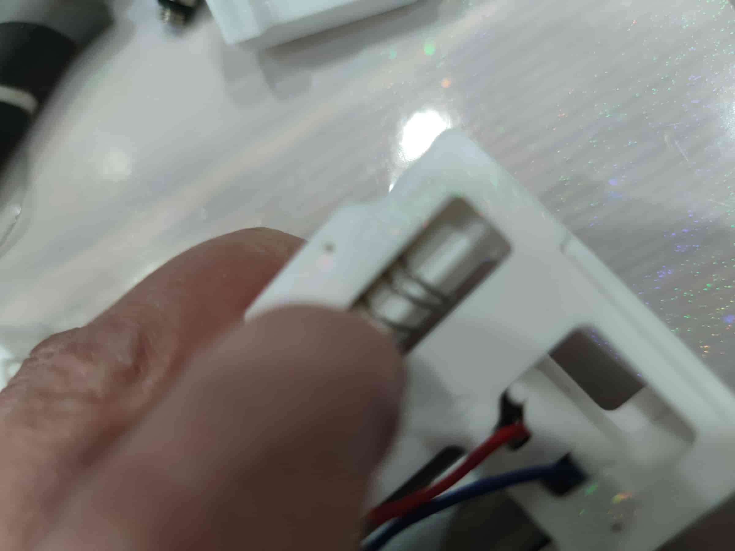
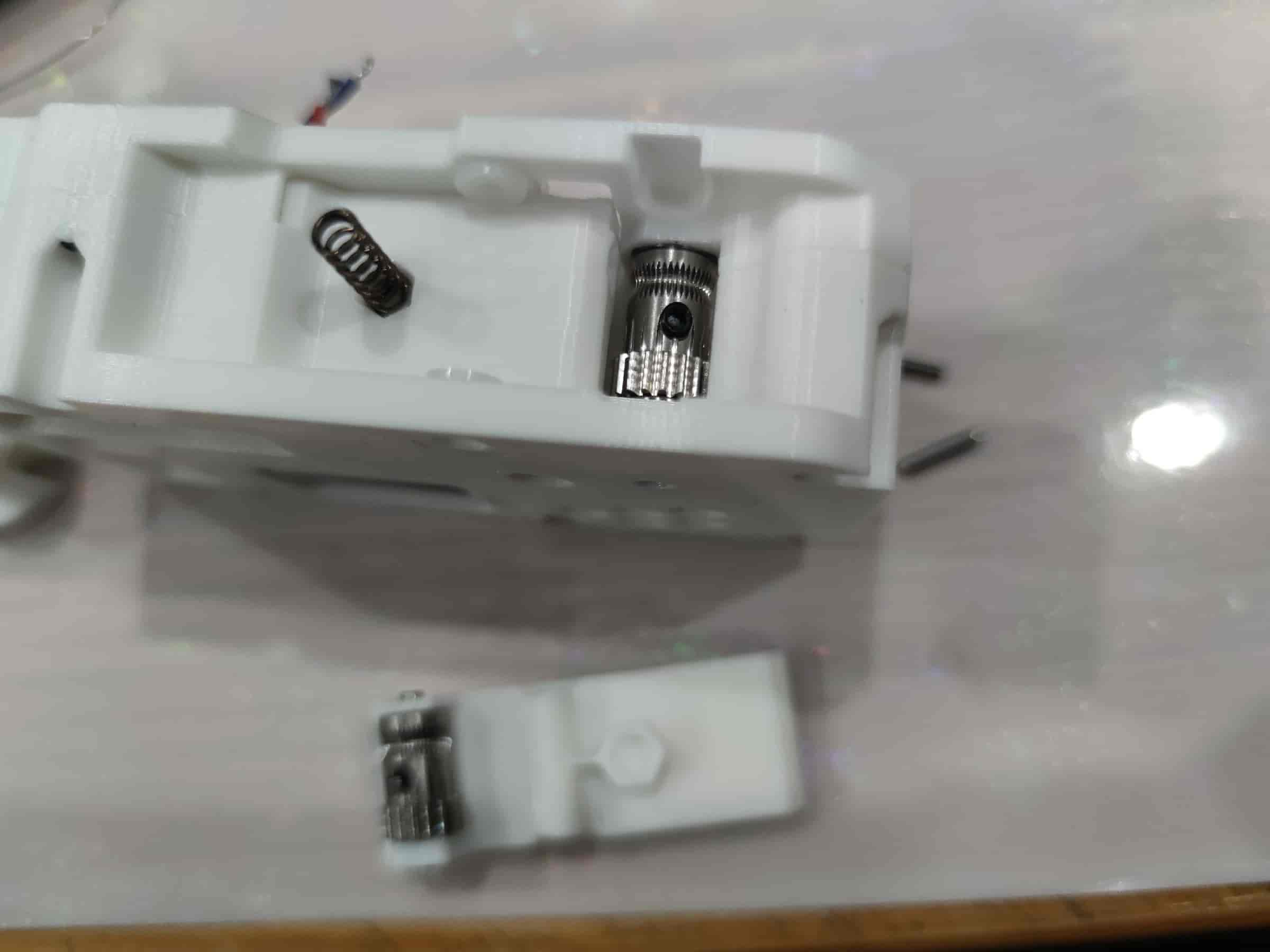
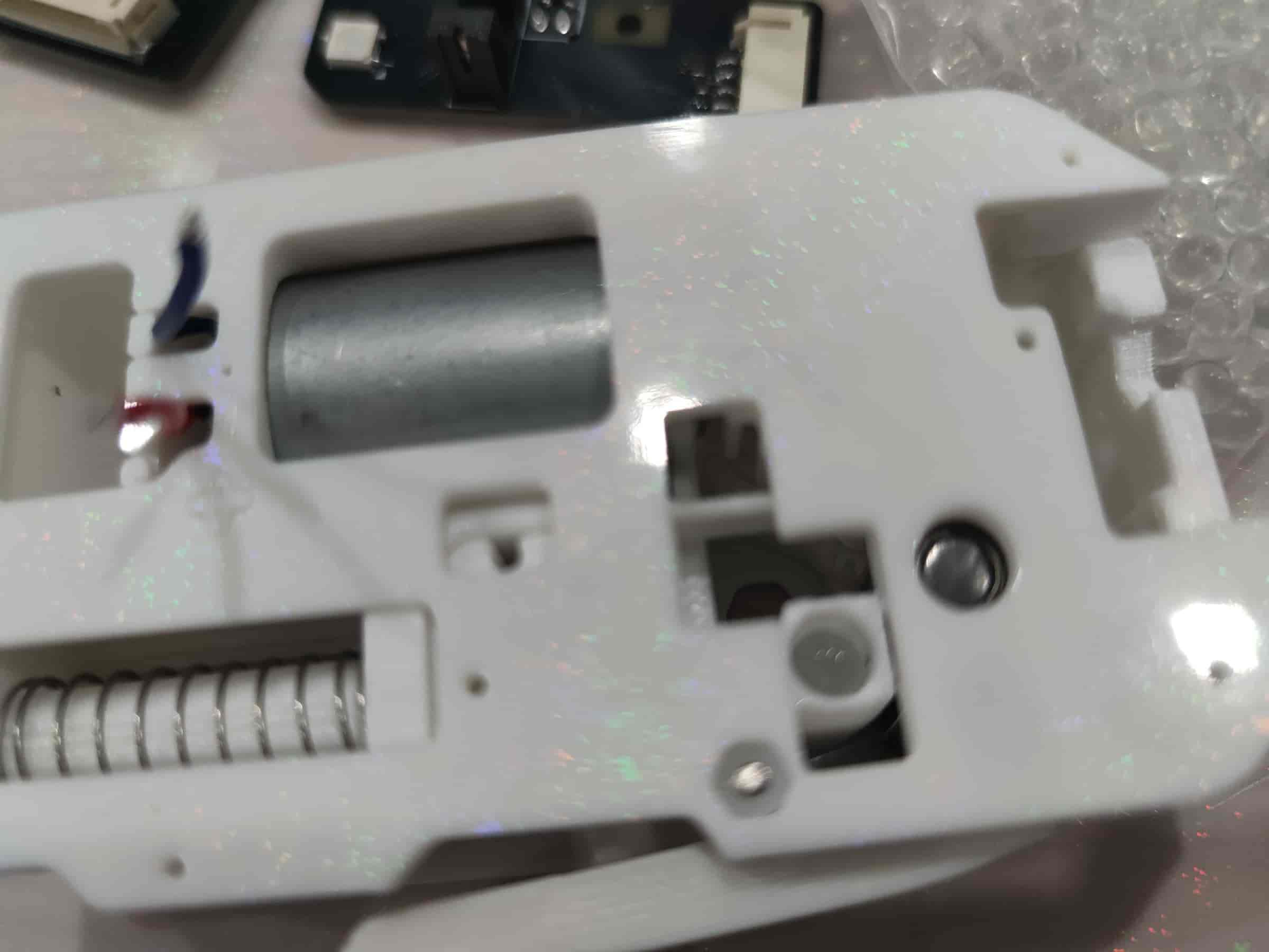
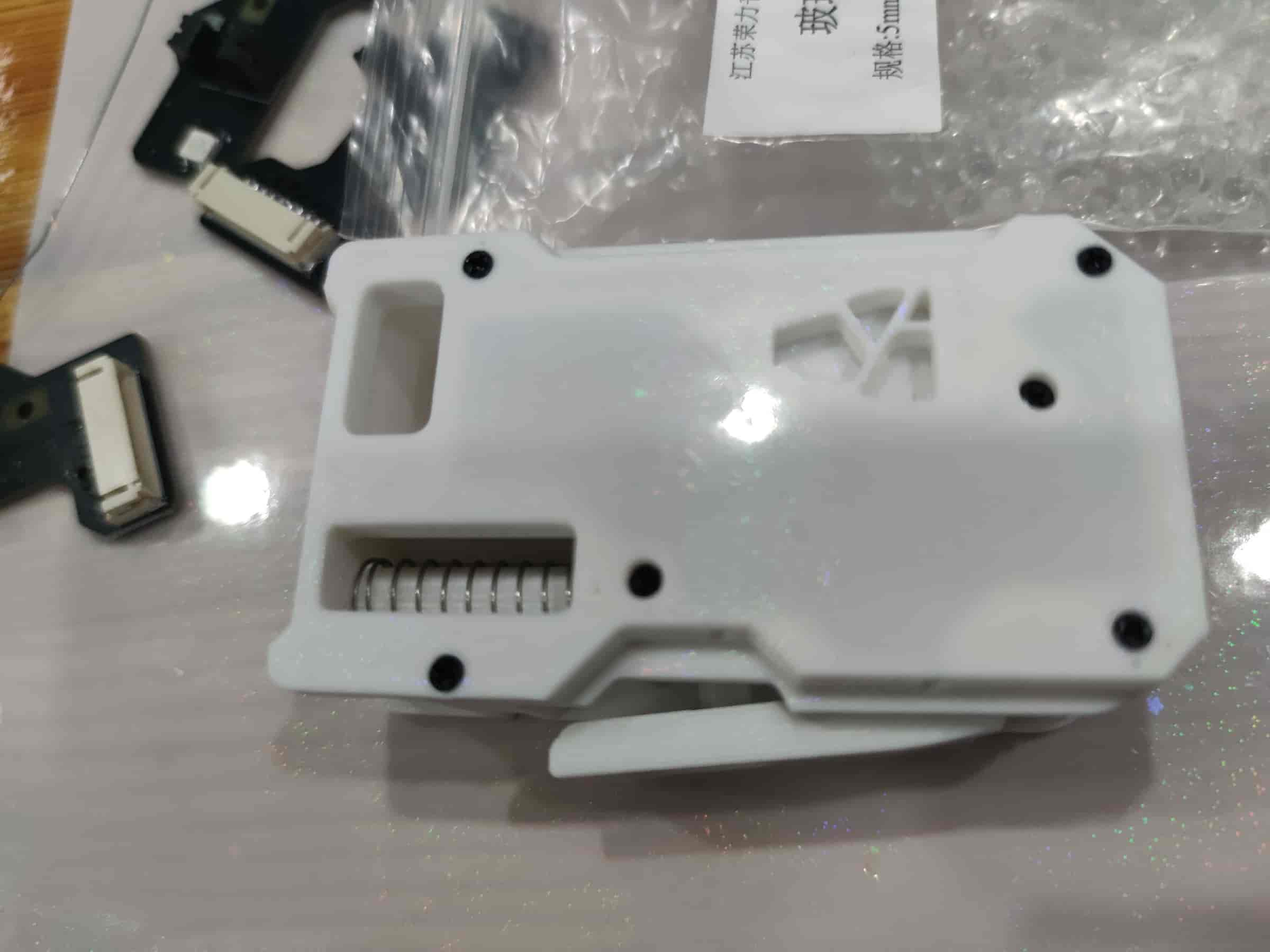
- Insert the buffer and spring. The recommended length for the original version is 35mm, and the extended version is 50mm.
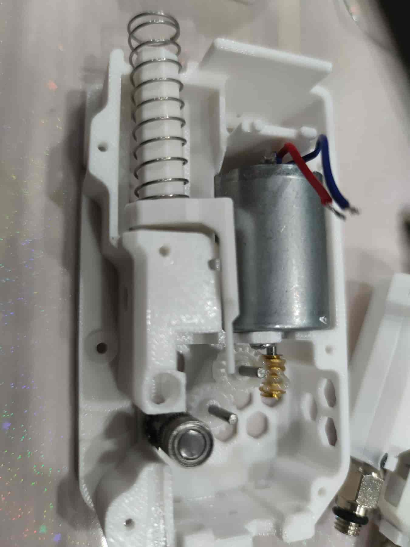
- Press the spring into the shell, ensuring it doesn’t pop out.
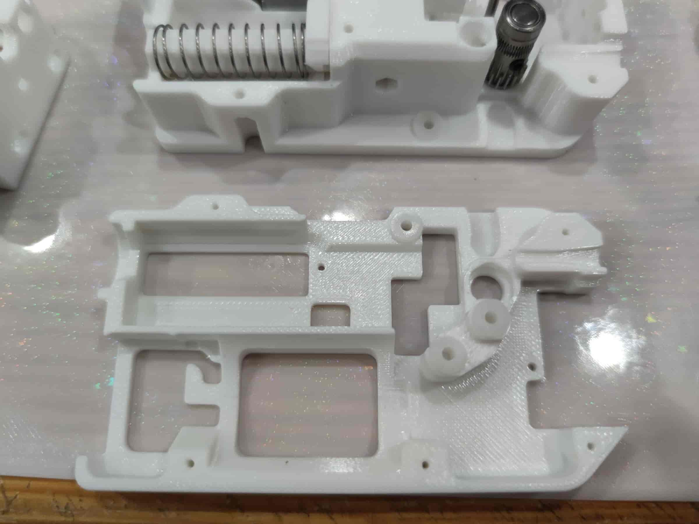
- Take out the middle frame printed part.
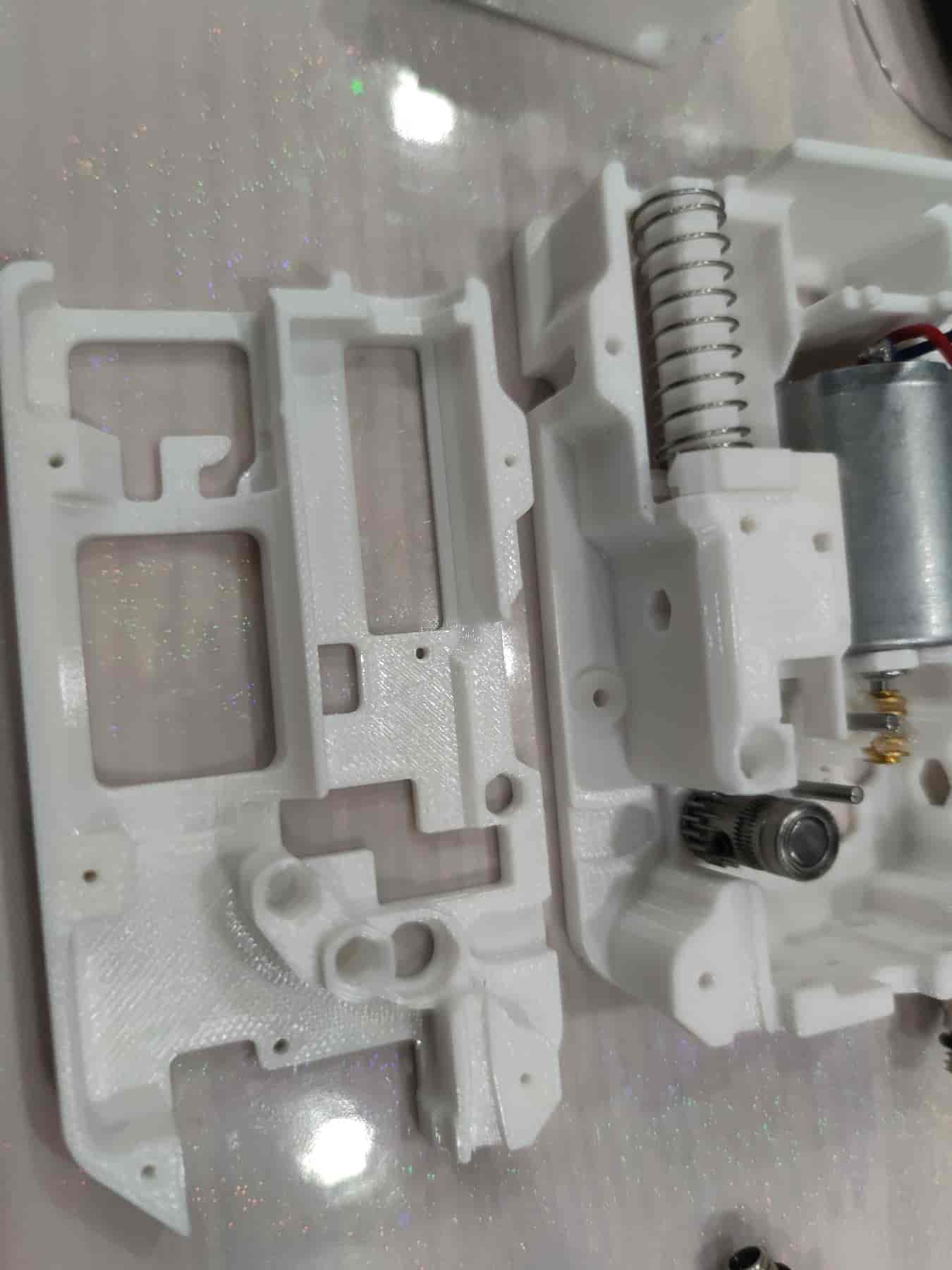
- Install three bushings into the middle frame, ensuring they are as tight as those in the bottom shell (usually, the middle frame bushings are easier to install).
- Prepare to install the middle frame. First, thread the motor wires out to the same length without pinching them. Ensure the gear shafts align with the bushing holes in the middle frame and the MR85ZZ bearing at the BMG gear aligns with its slot. Also, ensure the spring is inside the shell and not stuck. After installing the middle frame, try pressing the spring.
- How it looks after installation.
- Carefully flip it over, press firmly to reduce gaps, and tighten the five M2x8 self-tapping screws.
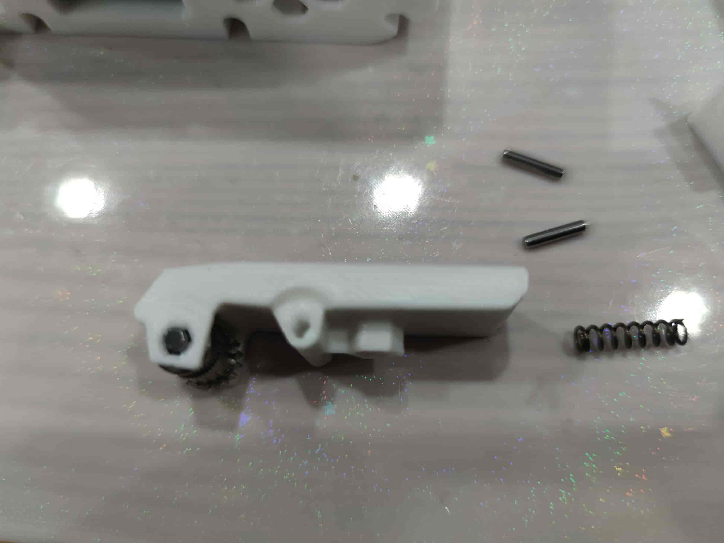
- Prepare to install the lever part: a 0.6x4x15 spring (recommended: 0.4x4x15), two M2x10 dowel pins, two ball bearings from the BMG kit, one dowel pin, and one BMG gear without holes (purchased from 1688 may all have holes).
- Insert the two ball bearings into the BMG gear.
- Take out the lever printed part (if not printed upright, it may need sanding) and place the BMG gear on it. Pay attention to the direction: the toothed side should face the thicker side.
- Stand it upright and press the dowel pin from the kit into place, ensuring it is centered on both sides.
- After installation, test the rotation of the BMG gear. It should rotate smoothly; otherwise, sand the printed part.
- Stand the feeding assembly upright and insert the lever spring (0.6x4x15, recommended: 0.4x4x15).
- Install the lever, ensuring the spring aligns with the hole.
- Hold the lever and assembly flat, ensuring the bushing and lever holes are aligned. Prepare to install the dowel pin.
- Insert the M2x10 dowel pin and press it in with a tool.
- Ensure it is installed properly and does not protrude beyond the shell.
- Flip to the other side, hold the lever flat, and press in another M2x10 dowel pin.
- Ensure proper installation, then proceed to the next step.
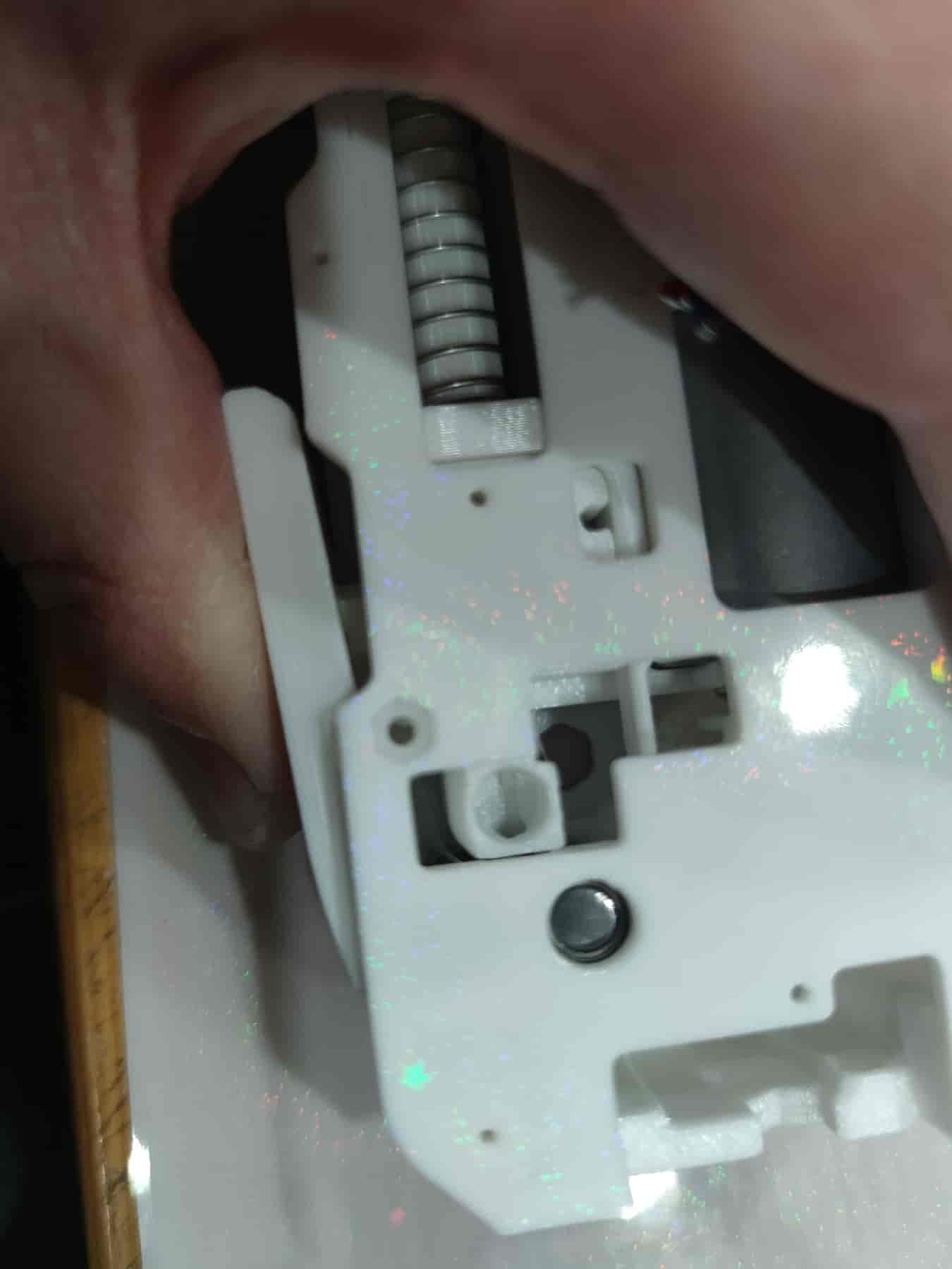
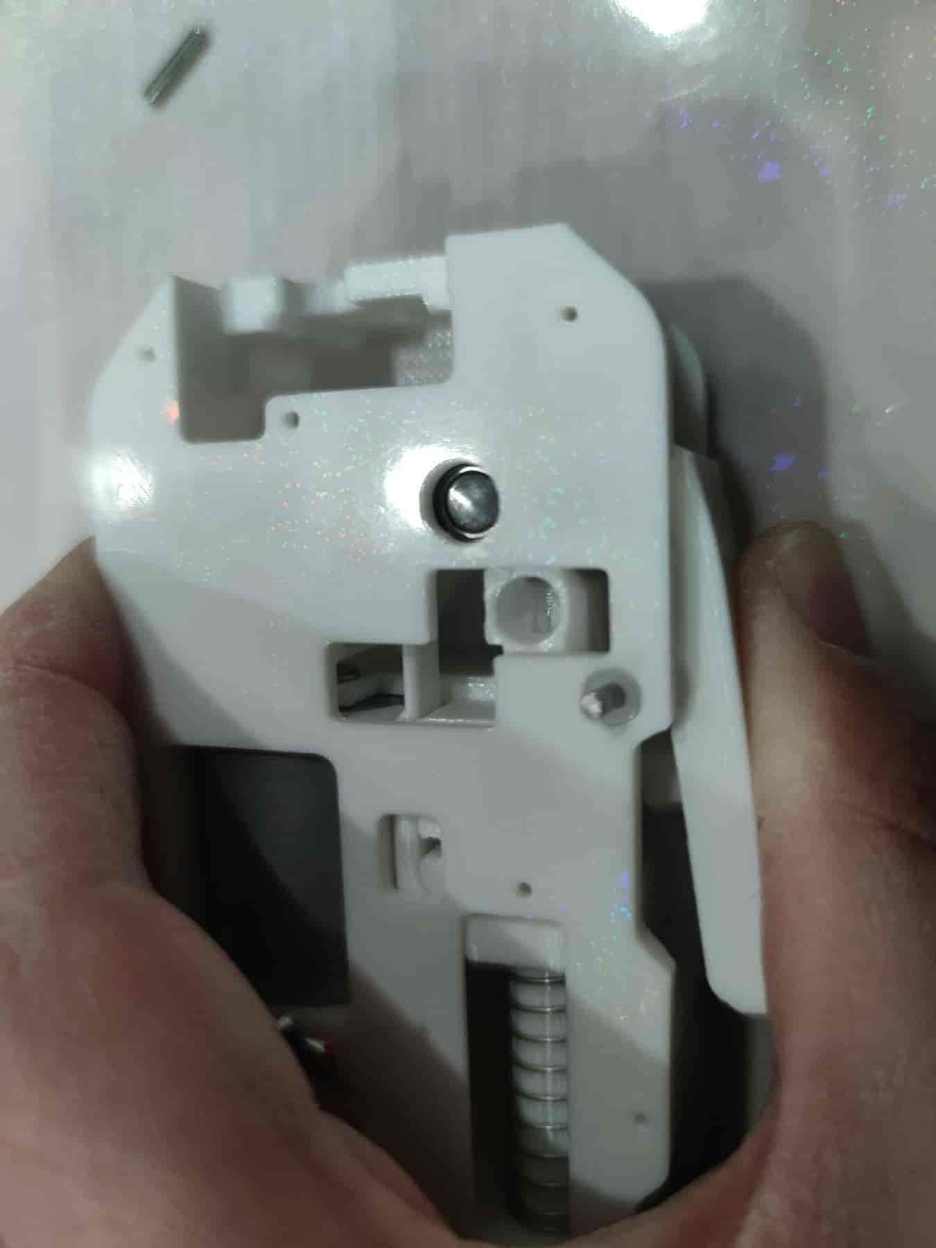
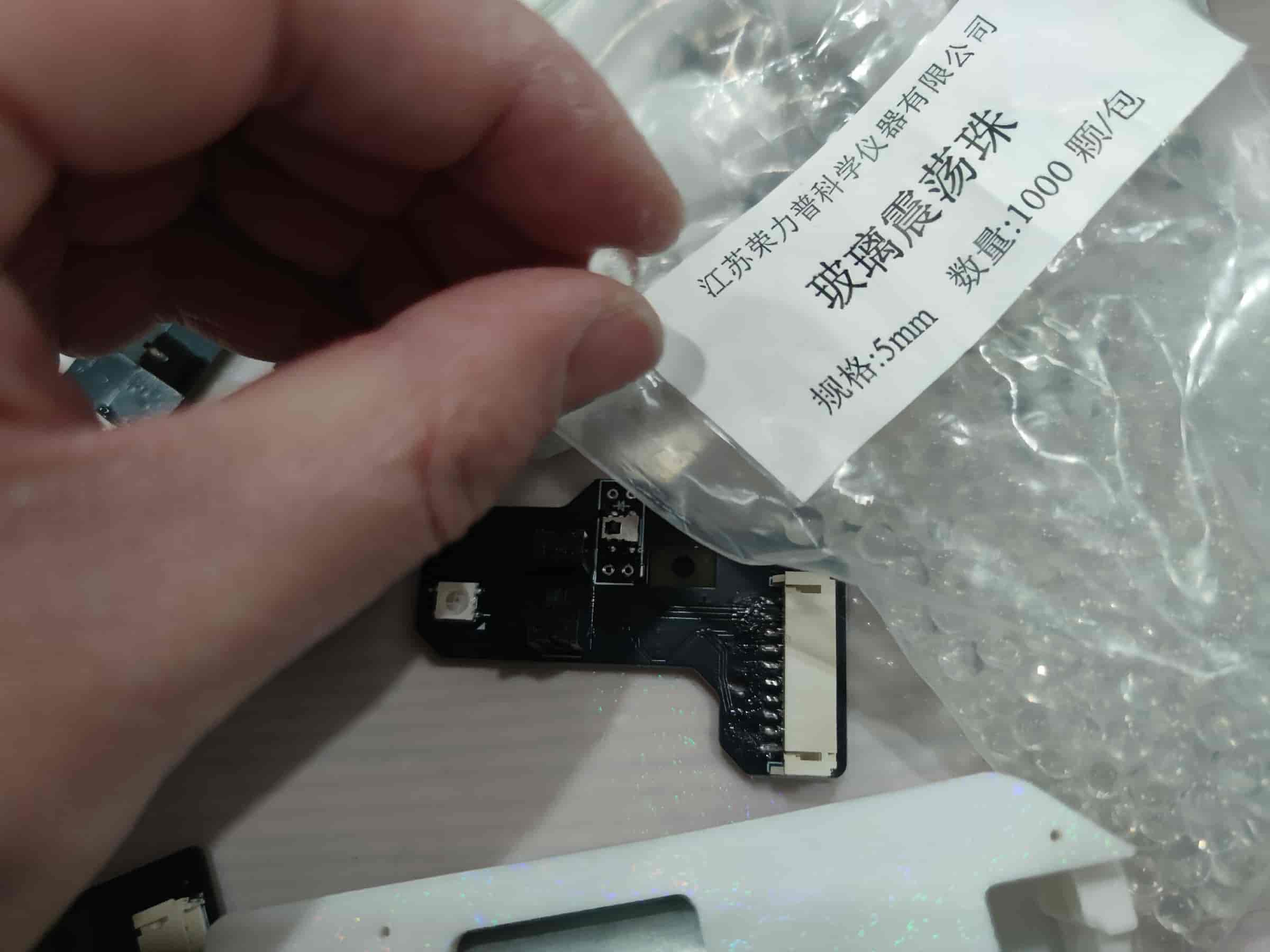
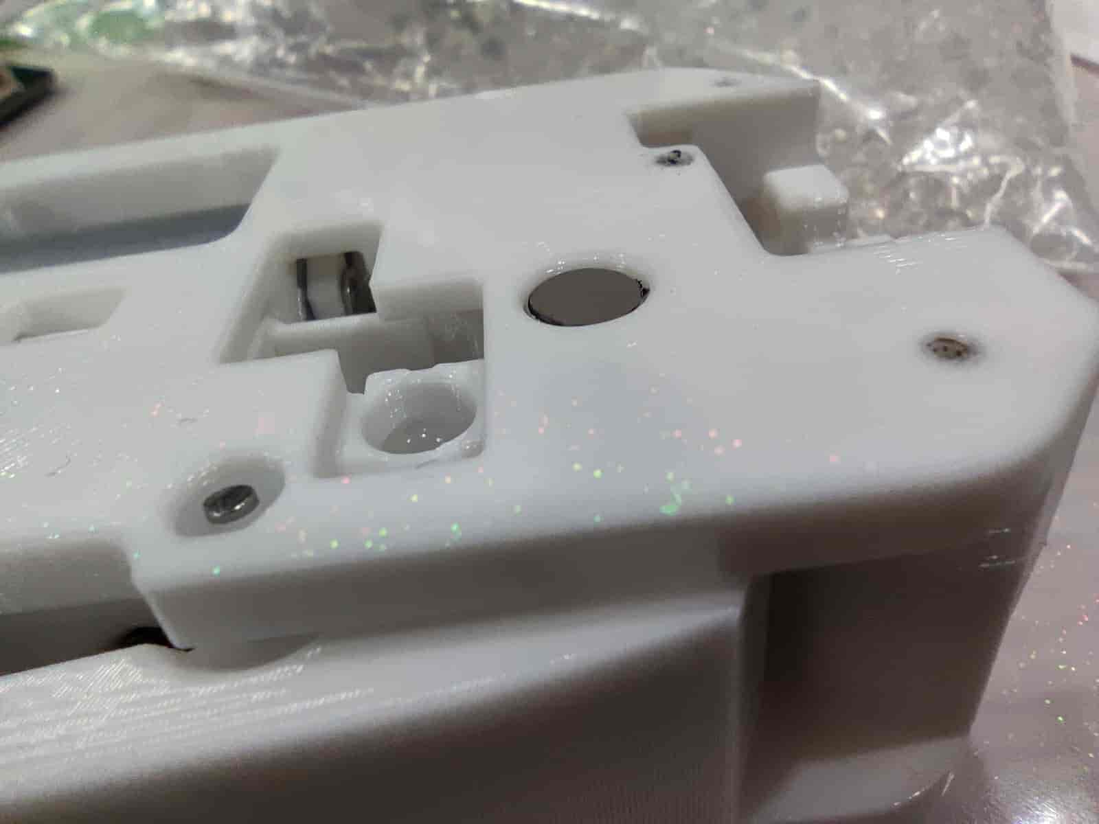
- Prepare a 5mm diameter glass bead (heavier alternatives like steel beads are not recommended).
- Place it into the hole, ensuring it can drop out easily when turned upside down.
- Install the radial magnet onto the BMG gear shaft. The radial magnet size is 6x2.5mm. After installation, there should be some distance between the magnet and the shell. If it doesn’t rotate, there’s an issue. Note: Regular magnets cannot replace radial magnets.
- Then place the component PCB.
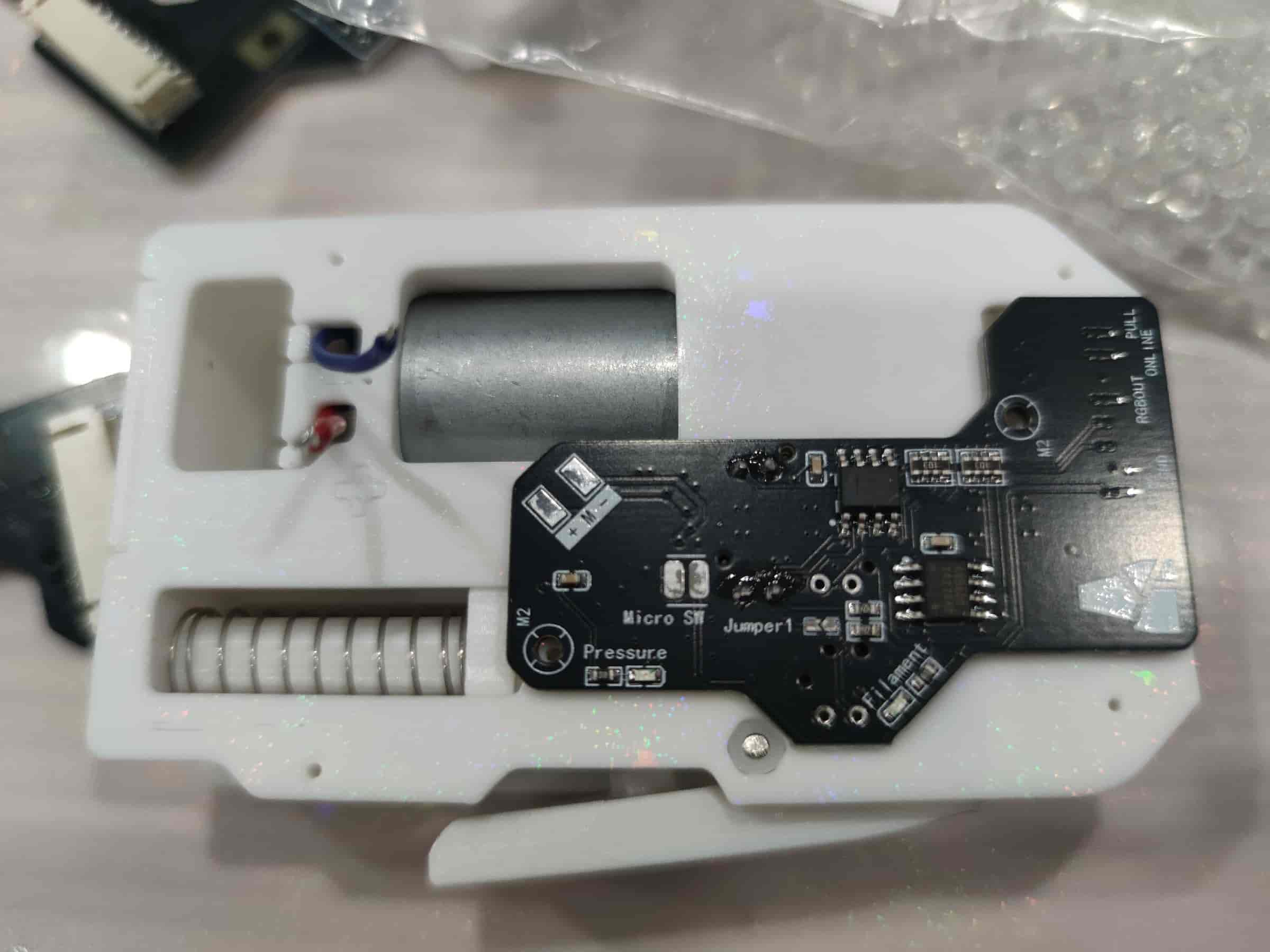
- Secure it with two M2x8 self-tapping screws. Tighten both screws gradually to avoid misalignment.
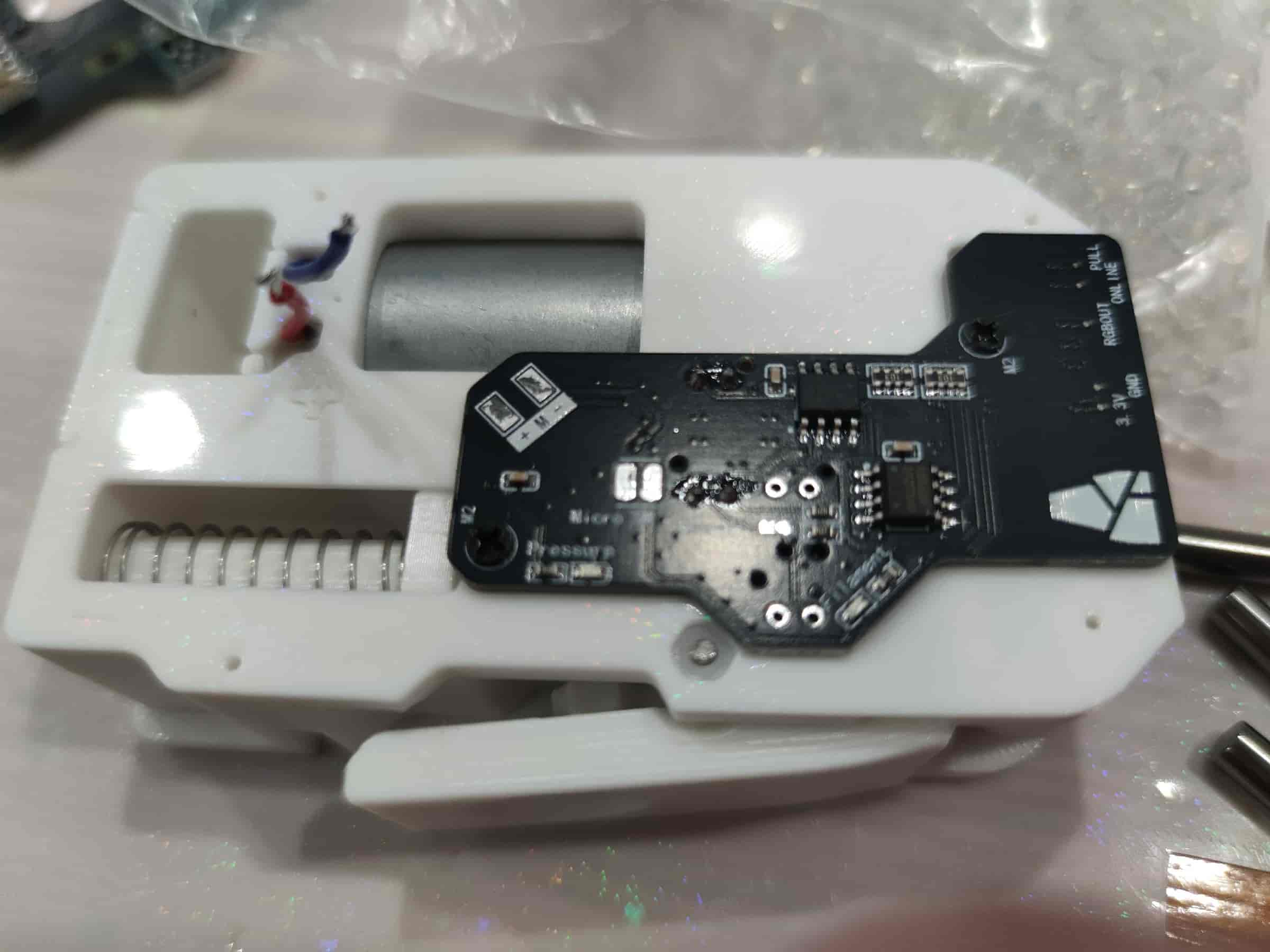
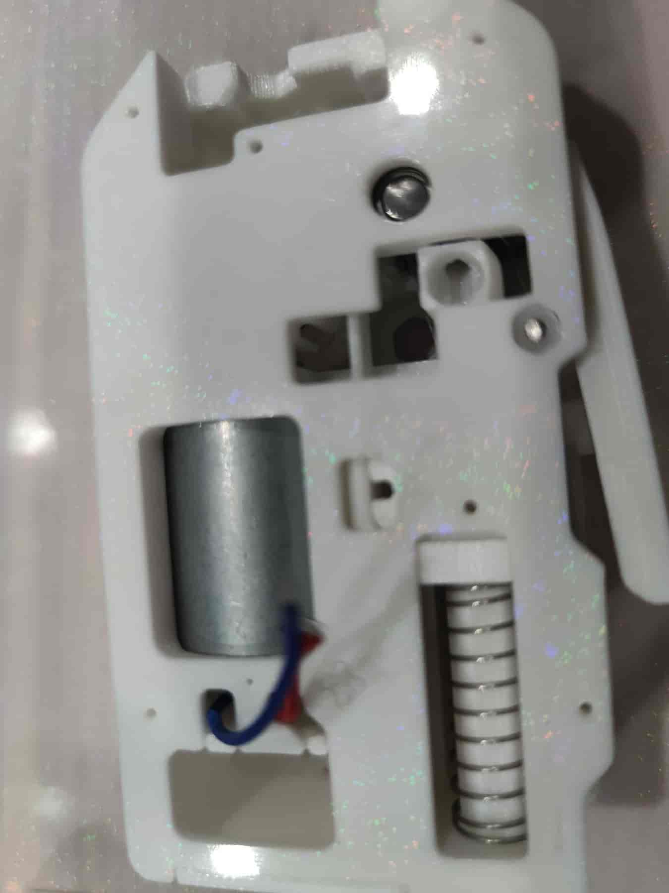
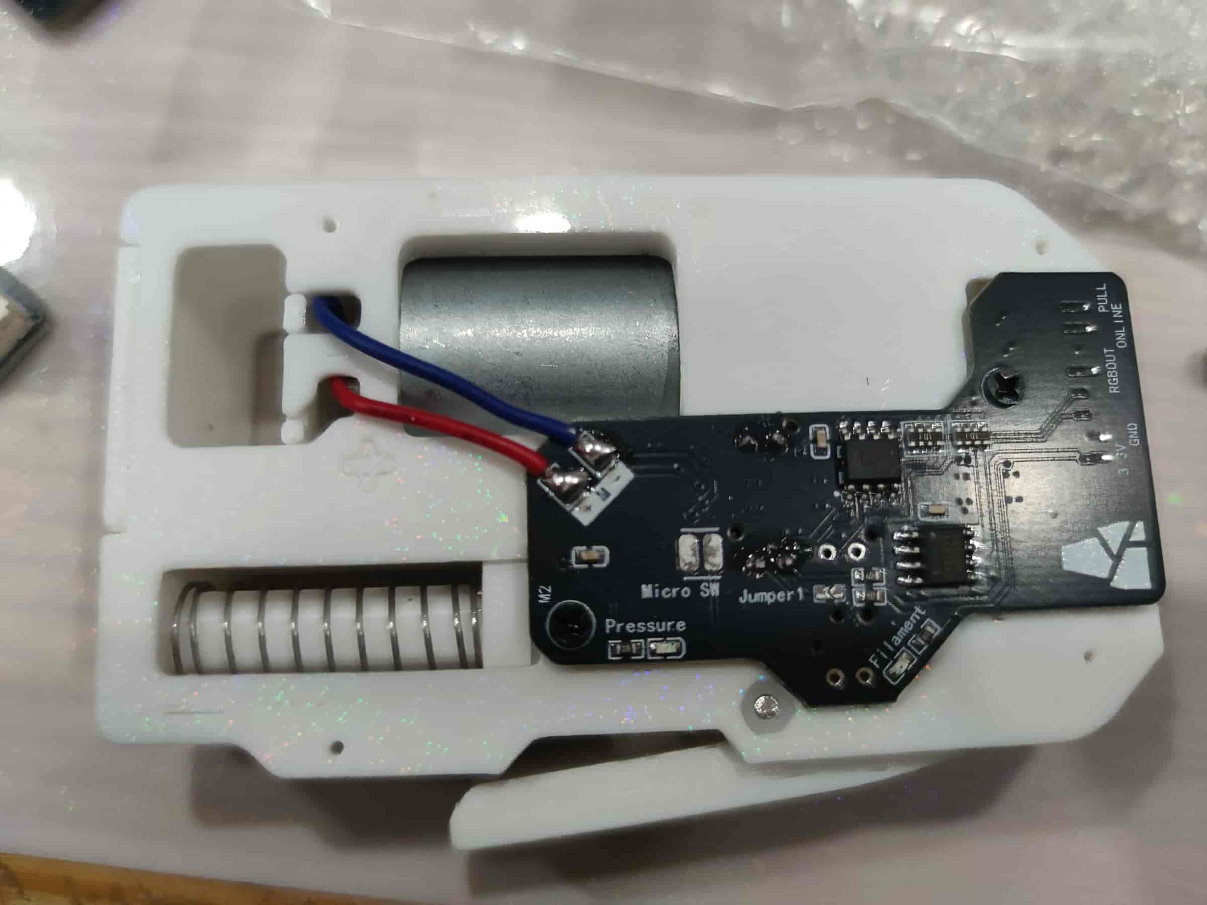
- Solder the motor wires. For older firmware (e.g., 130), ensure correct polarity to avoid reverse motor rotation. For newer firmware (from 3-14 onwards), the BMCU automatically determines the direction.
- Place the top cover plate, ensuring it doesn’t pinch the wires or leave gaps.
- Tighten the four M2x8 self-tapping screws. Congratulations, you’ve completed the assembly of one channel!
Note
The number of feeding components determines your multi-color channels. To make the device functional, you need to install 2-4 feeding components.
Final Assembly
- To be continued...