

From Beginner to Finished Product: BMCU Manufacturing (BMCU Assembly Tutorial) Truly Step-by-Step
INFO
This tutorial was created by group member @少年谈情不说爱℡ and slightly modified by @wanzi
INFO
Another group member @晓心乐子人 has created a video tutorial
This version and its derivatives are not the latest and are outdated, no longer maintained by the Bambu Lab team
v1.1 & v1.31
130 Improved Shell Version
Acknowledgments to 4061N and Parentheses for Open Source
Author: 山竹 (Shanzhu)
Preface
BMCU is primarily open-sourced by 4061N, with Parentheses contributing to the BMCU component framework and the design of the BMCU-to-printer bracket.
BMCU is designed with four channels as one unit, currently using the CH32 microcontroller as the main control. All required design references are based on publicly available online materials and personal testing. The program is developed on the Platform IO platform using the Arduino support library for CH32 microcontrollers and incorporates the CRC library by robtillaart. Note: This project follows the GPL2.0 open-source license, with the additional stipulation that it is prohibited for commercial use.
BMCU is intended for DIY learning and must be used with Bambu Lab printers A1 or A1mini to achieve functionality similar to AMS lite, enabling multi-color and multi-filament printing with automatic filament switching and feeding. However, it lacks the RFID automatic filament recognition feature. We still recommend purchasing the official Bambu Lab AMS lite for better reliability. Please note that DIY projects come with inherent risks, and the author is not responsible for any resulting issues.
This project requires basic soldering skills. Beginners should seek separate soldering tutorials, as this guide does not cover basic soldering techniques.
Source Address: https://gitee.com/at_4061N/BMCU
Written: 20250124-20250215
PCB Ordering Tutorial
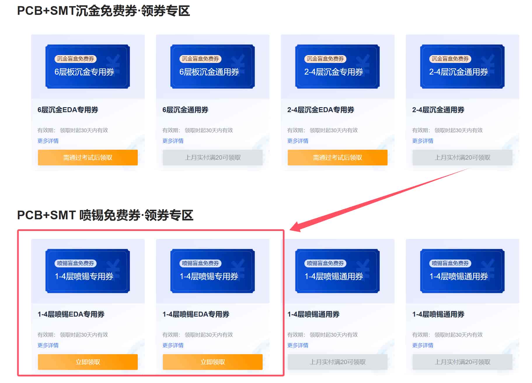
- Open the JLCPCB ordering platform: https://member.jlc.com/?spm=PCB.Homepage.functionbar.1023, register, and log in. First, claim the two monthly coupons (All Menu → User Center → Coupon Center → Free Coupons). Each coupon allows free production of up to 5 boards (10x10cm).

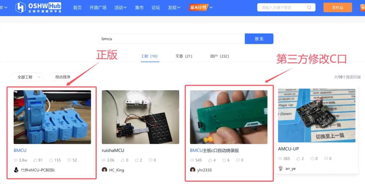
- Open and log in to the JLCPCB hardware open-source platform: https://oshwhub.com/.
Search for BMCU and choose between the official pin-programming V1.1 board or the third-party modified USB-C programming V1.31 board, depending on your needs. Different interfaces will require different base shells later.
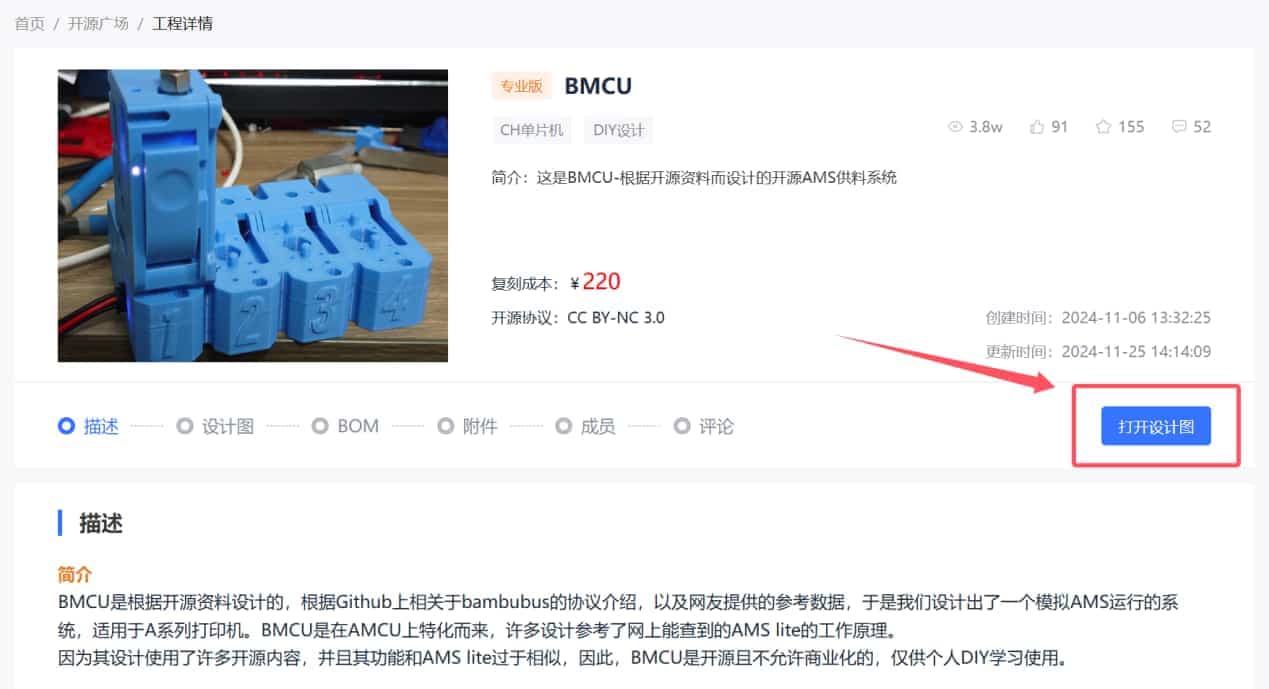
- Open the design files (including the mainboard and sub-board).
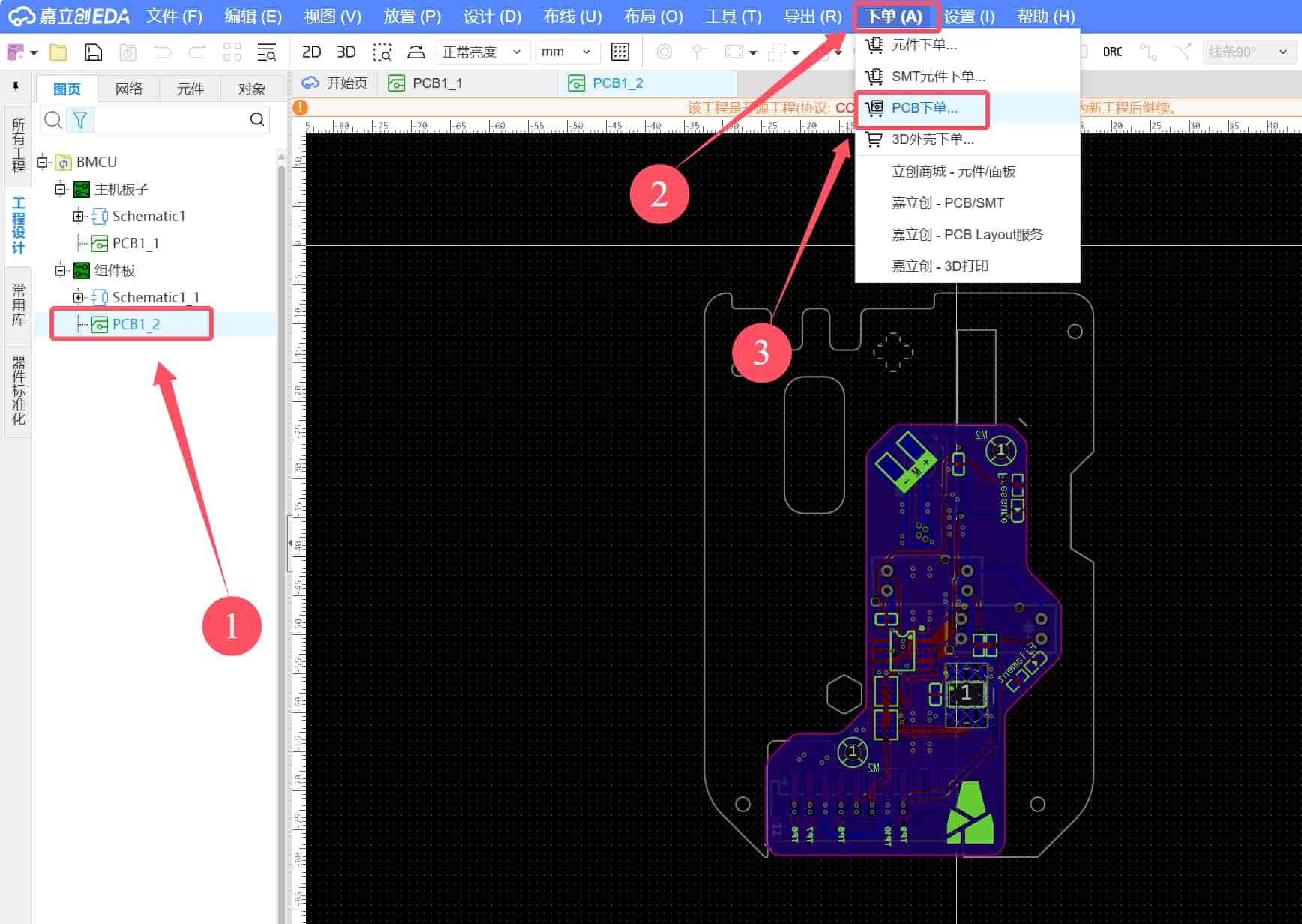
- First, select PCB1-1 (mainboard). You can manually panelize the boards or order them directly. Then, select Order → PCB Order.
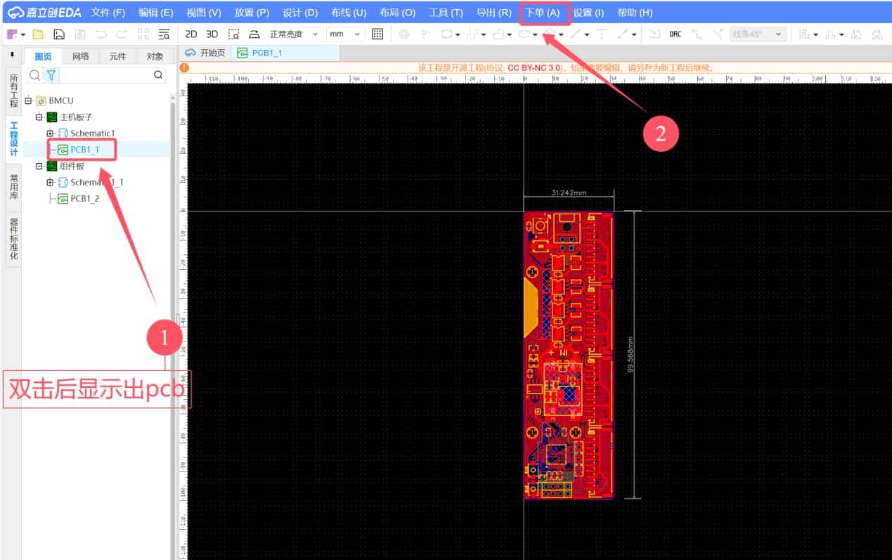
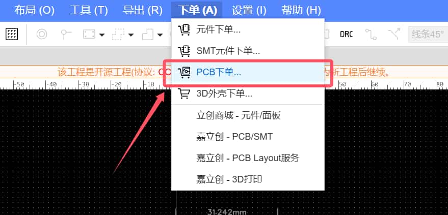
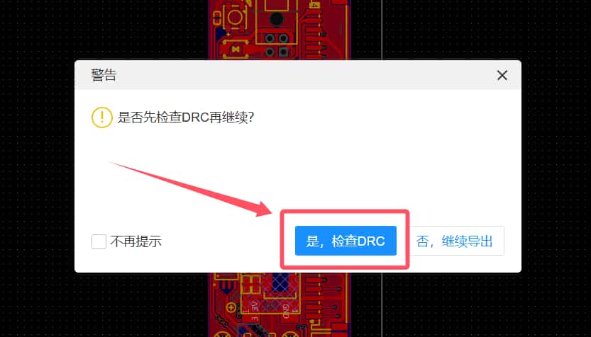
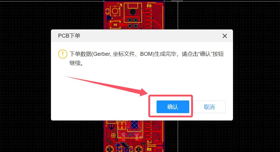
- A pop-up will appear. Select "Yes, check DRC" (if no pop-up appears, ensure you are logged in). If no errors are found, confirm via the pop-up.
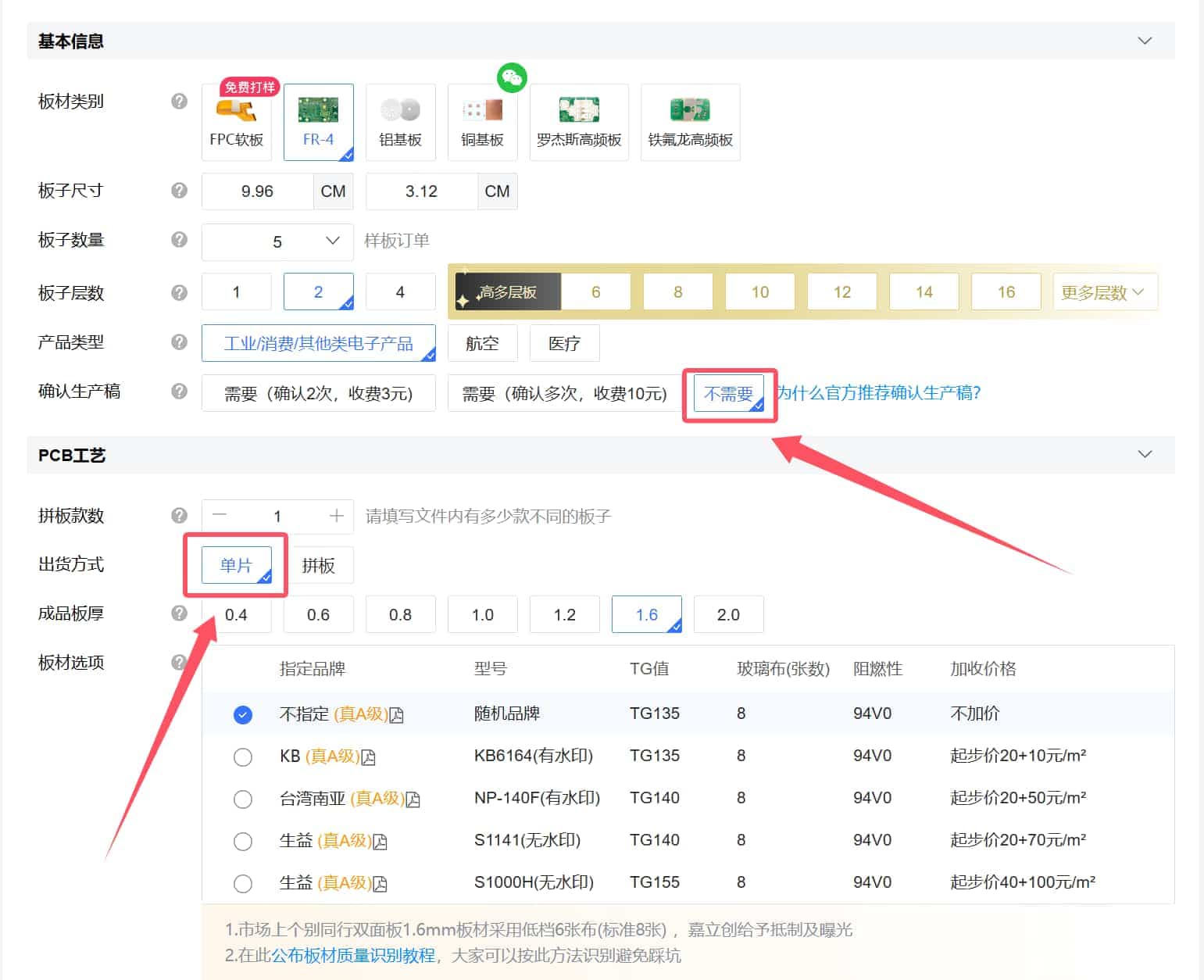
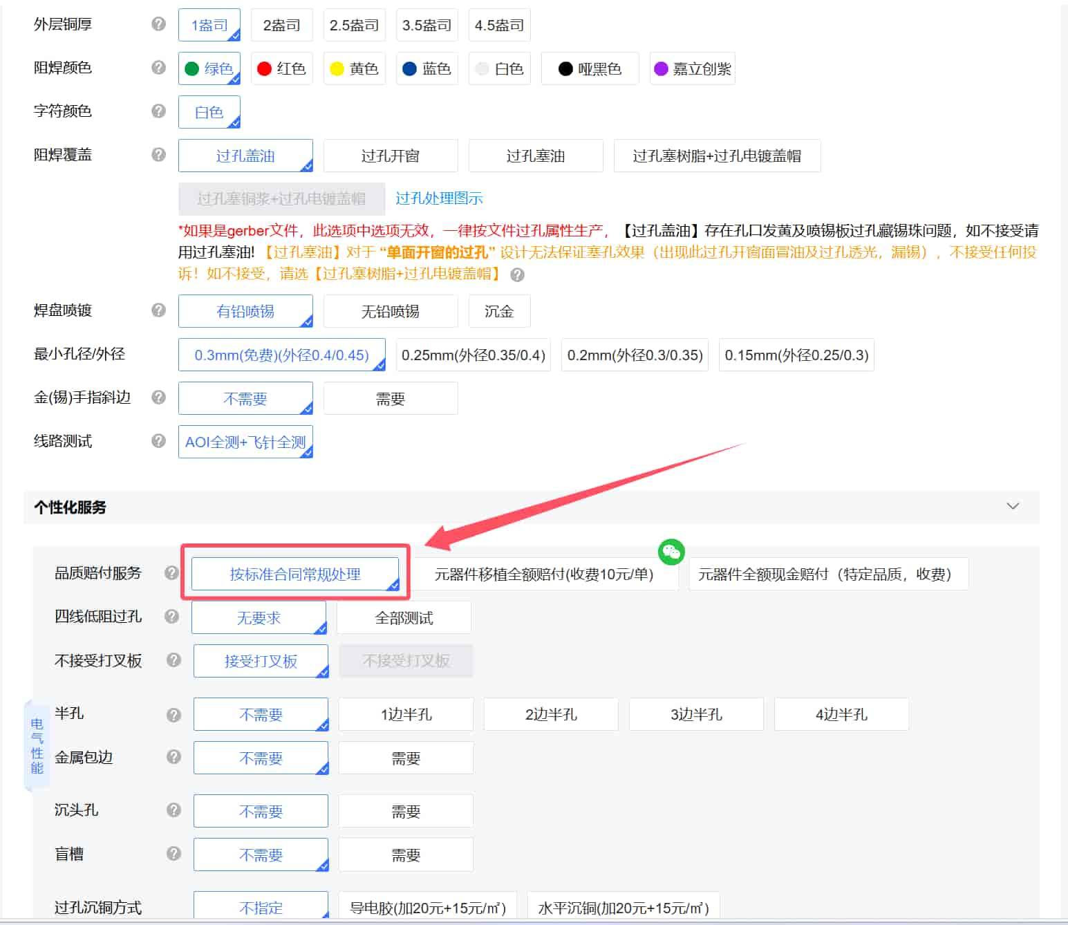
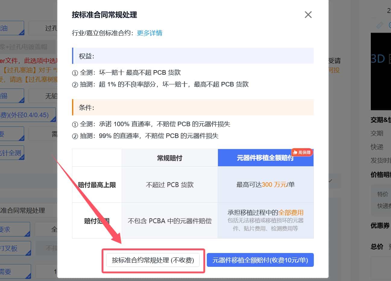
- Follow the images to select the options.
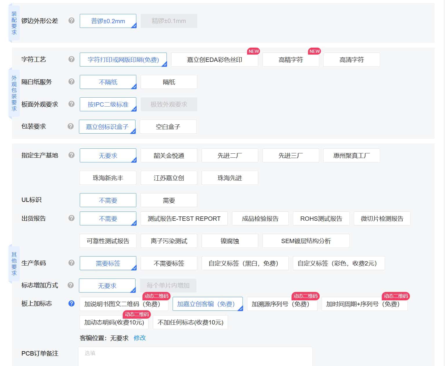
- Follow the images to select options and fill in your invoice details.
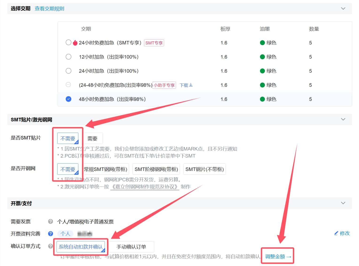

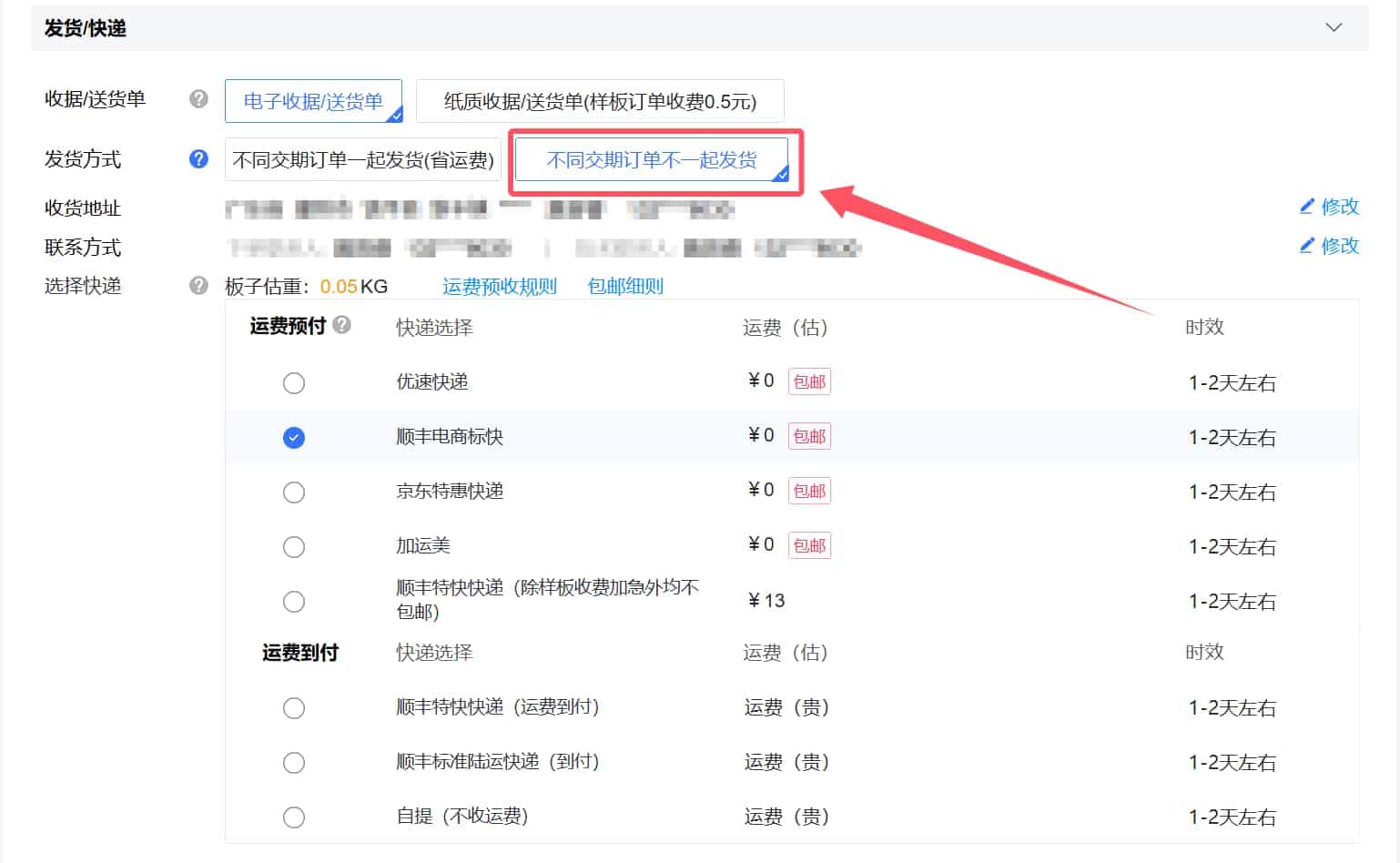
- Follow the images to select options, enter your phone number and shipping address, and choose your preferred courier.
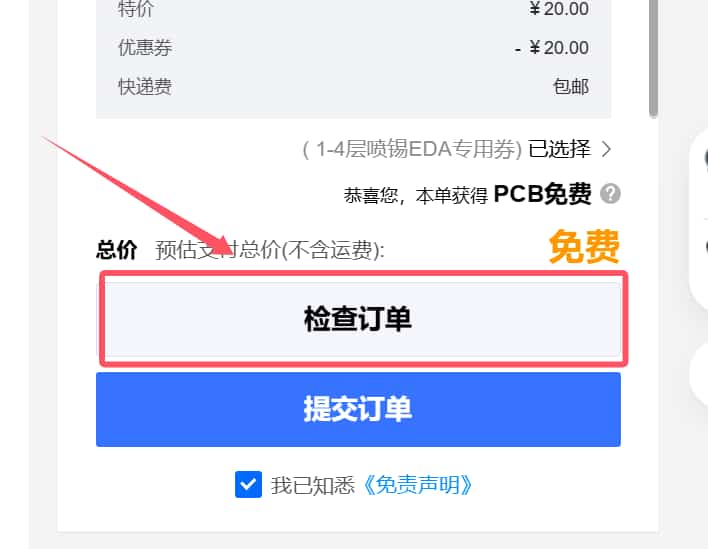
- Apply the coupon. After confirmation, the total should show as free.


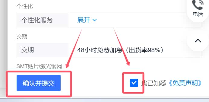
- Review the order. If everything is correct, submit the order and confirm payment (should be ¥0). If it’s not free, there may be an error or the order may not meet coupon requirements.
- Repeat the above steps to order PCB1-2 (sub-board). This completes all PCB orders. By default, this will order 5 mainboards (PCB1_1) and 5 sub-boards (PCB1_2) (one BMCU set requires 1 PCB1_1 and 4 PCB1_2).
Materials and Soldering Tools
Refer to the materials list: (Full Bill of Materials)
Soldering Tools:
- Soldering iron (recommended models: T12, C210, 245)
- Hot plate/hot air gun (recommended: WY858 hot air gun)
- Solder paste/solder wire (recommended: medium-temperature 183°C)
- Flux
- Tweezers
Soldering auxiliary tools (included in the package):

Note for beginners:
- Chips must be soldered with the dot marking aligned correctly.
- RGB LEDs must be soldered with the triangle marking aligned correctly.
- Resistors and capacitors are non-directional.
- SMBJ24CA components are non-directional.
- Pin headers must be soldered in the correct positions.
- Motors must be soldered with the correct polarity (marked on the PCB).
- Photoelectric sensors must be soldered with the correct orientation.
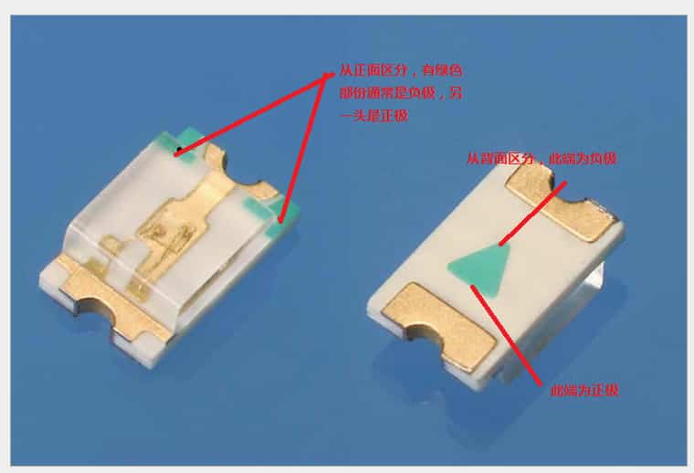
- LED indicators must be soldered with the correct polarity.
WARNING
Before powering on, thoroughly inspect the PCB for solder bridges, shorts, cold joints, or incorrect component orientation to avoid permanent damage! Take photos and share them in the group for reference, and check against the Ground Value Reference.
Mainboard and Sub-board Overview
- Mainboard Diagram:
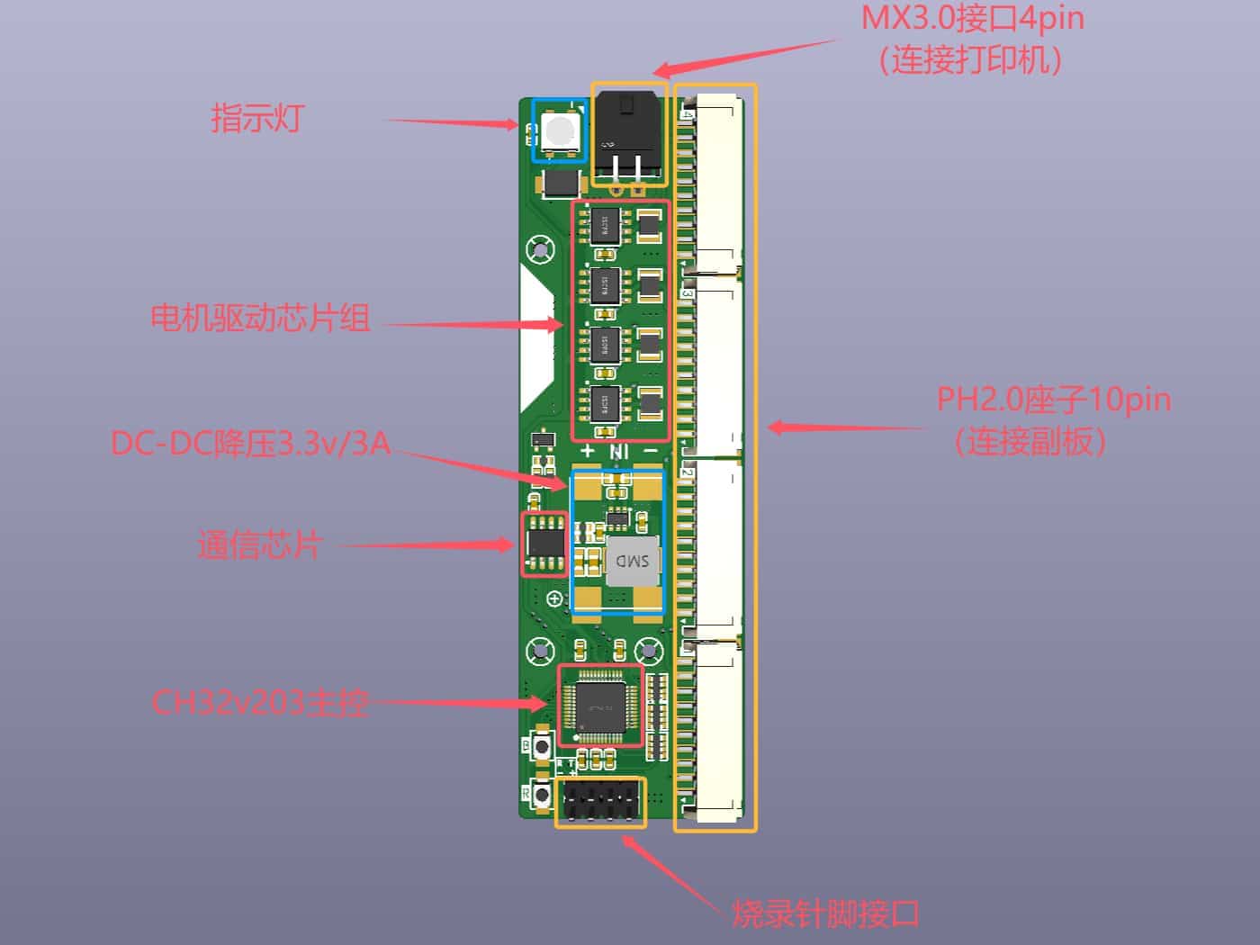
- R button: Chip reset button.
- B button: Boot0 button (pulls the chip into programming mode).
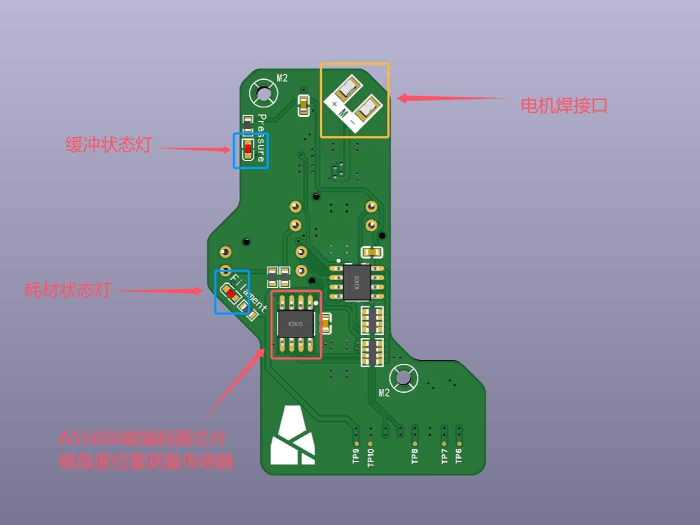
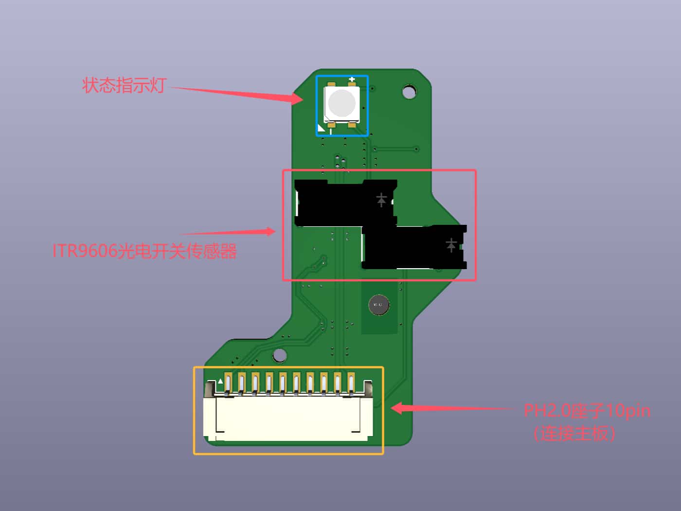
- Sub-board Diagram:
Firmware Flashing
IMPORTANT!!! Before flashing the firmware, ensure there are no solder bridges, shorts, cold joints, or incorrect component orientations on the PCB. Otherwise, the board may be damaged.
Testing method:
- Use a multimeter in continuity mode to check for shorts between the positive and negative terminals of the voltage regulator (no beep means normal).
- Check capacitors for continuity (normally no beep).
- Check for shorts between the 3.3V and GND pins (no continuous beep).
- Use the multimeter in resistance mode to verify resistor values are within the correct range.
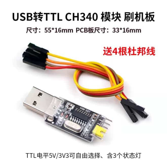
- Recommended USB-to-TTL module (fewer issues):
- Follow the firmware flashing tutorial and precautions.
Note: For the USB-C version, failing to remove protection on the first flash attempt is normal. Just proceed with the download. For subsequent flashes, remove protection twice until successful before downloading.
LED Indicator Meanings

BMCU Assembly
Step 1: Pre-Assembly PCB Testing
- Ensure the BMCU mainboard firmware (V0.2) is successfully flashed (red LED lights up when powered via USB-to-TTL; blue LED lights up when connected to the printer via MX3.0 4-pin cable).
- Ensure the sub-board functions correctly:
- When powered via USB: The RGB LED should be blue (port 1 blue, ports 2-4 off; blinking is normal). The two photoelectric sensor LEDs should be off. When the sensor is blocked, the corresponding backlight should turn on. The feed RGB LED turns blue; the jam RGB LED turns red.
- When powered by the Bambu Lab printer: Both the mainboard and sub-board RGB LEDs should be blue. The photoelectric sensor LEDs should be off. When blocked, the backlight turns on, and the RGB LED remains blue.
- Ensure proper communication between the mainboard, sub-board, and printer. When connected, the printer's filament menu should show the AMS option, and blocking the sensor should display the filament.
Step 2: Mechanical Assembly Part 1 (Feeder Unit, 4 Units Required for 1 Set)
- First, print one feeder shell and test for fit before printing the rest to avoid material waste. This tutorial uses this model: https://makerworld.com.cn/models/741793 (modified by 青铜板子cn).
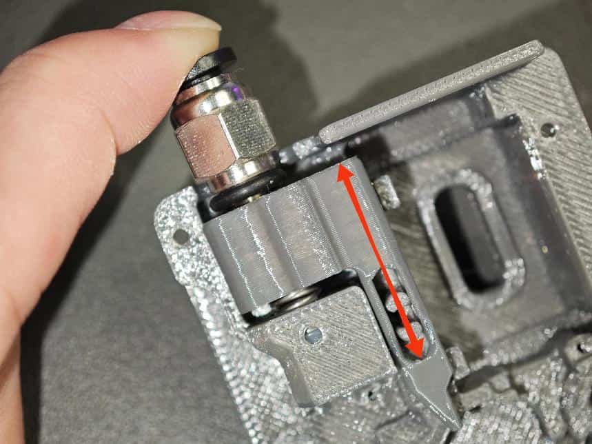
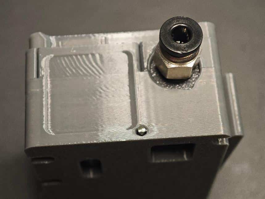
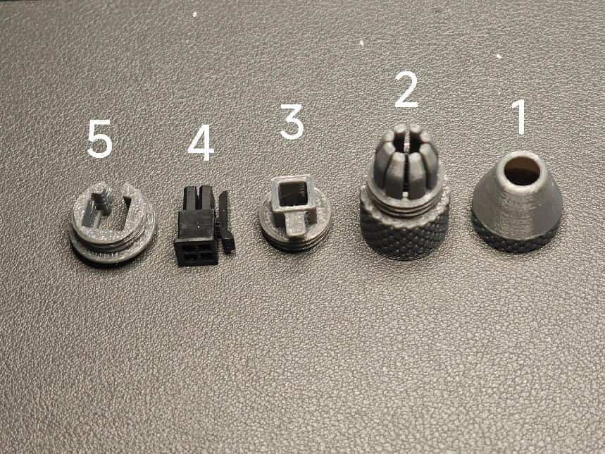
- Screw the pneumatic fitting (PC4-M6 passthrough) into the buffer assembly. Avoid misalignment.
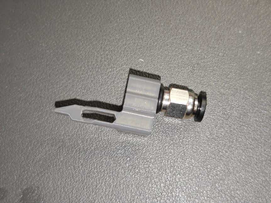
- Take one large spring (0.5×6×10mm) and a 62B bushing. Assemble as shown.
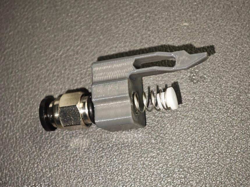
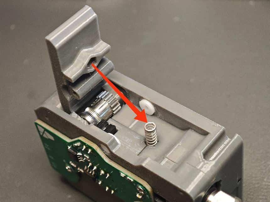
- Compress the spring and insert it into the base shell (keep the spring vertical to avoid jamming).
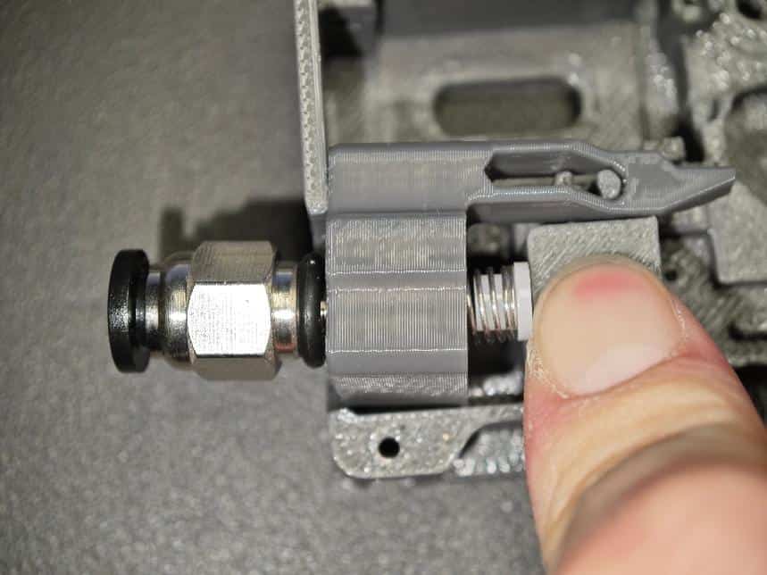
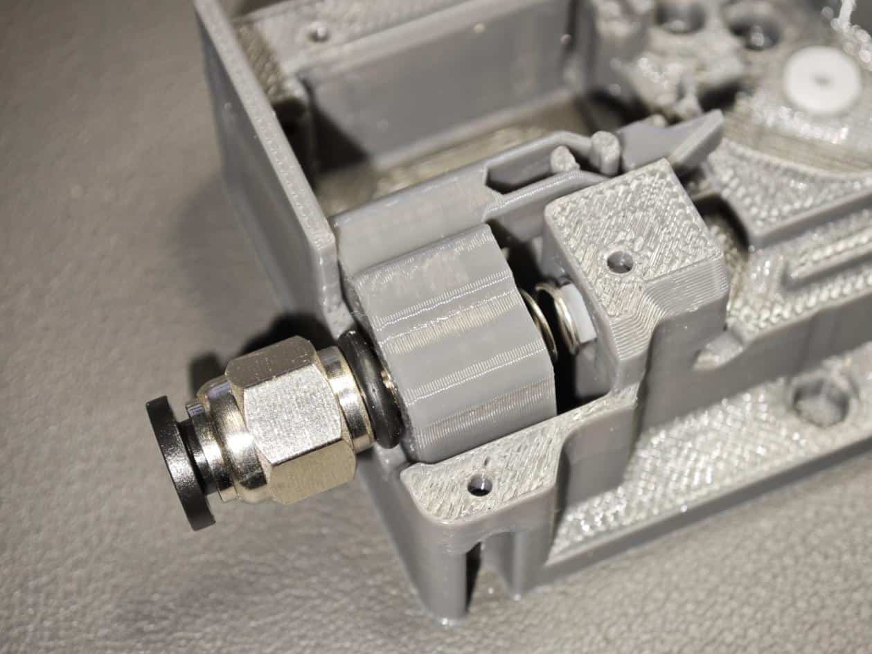
- Ensure the assembly moves smoothly.
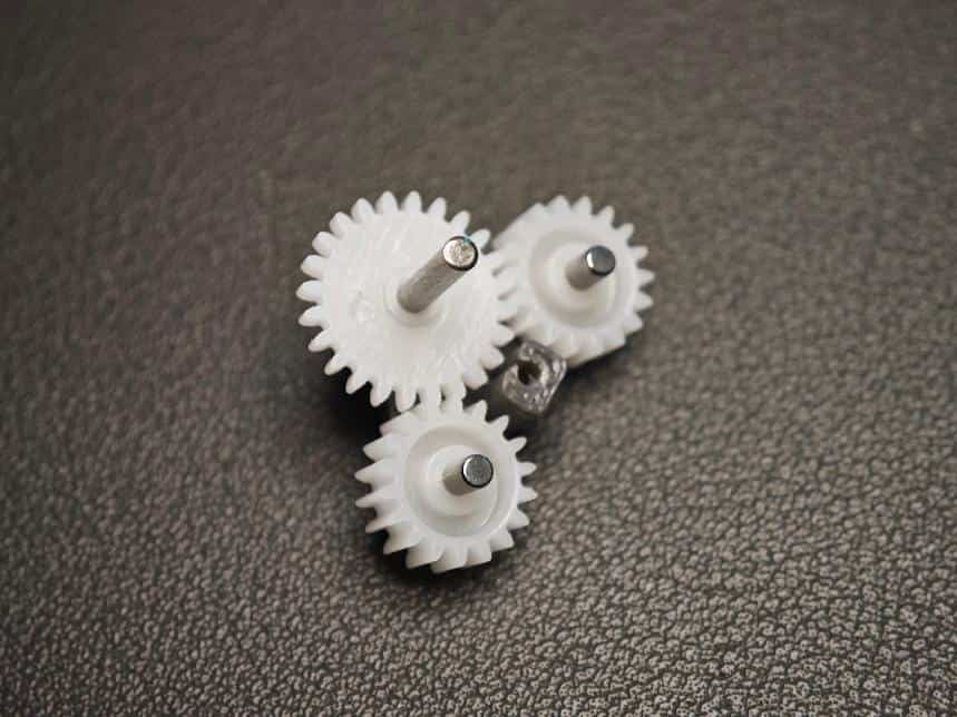
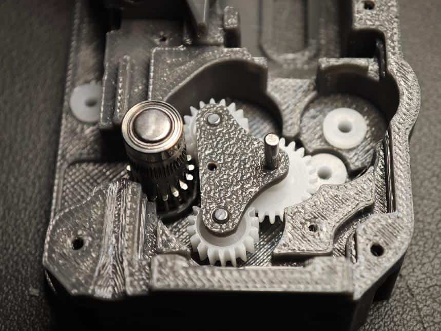
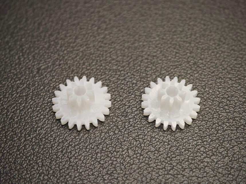
- Assemble the gear mechanism. Take two small gears (182A) and short shafts (2×10mm). Assemble as shown (ensure equal shaft length on both sides).
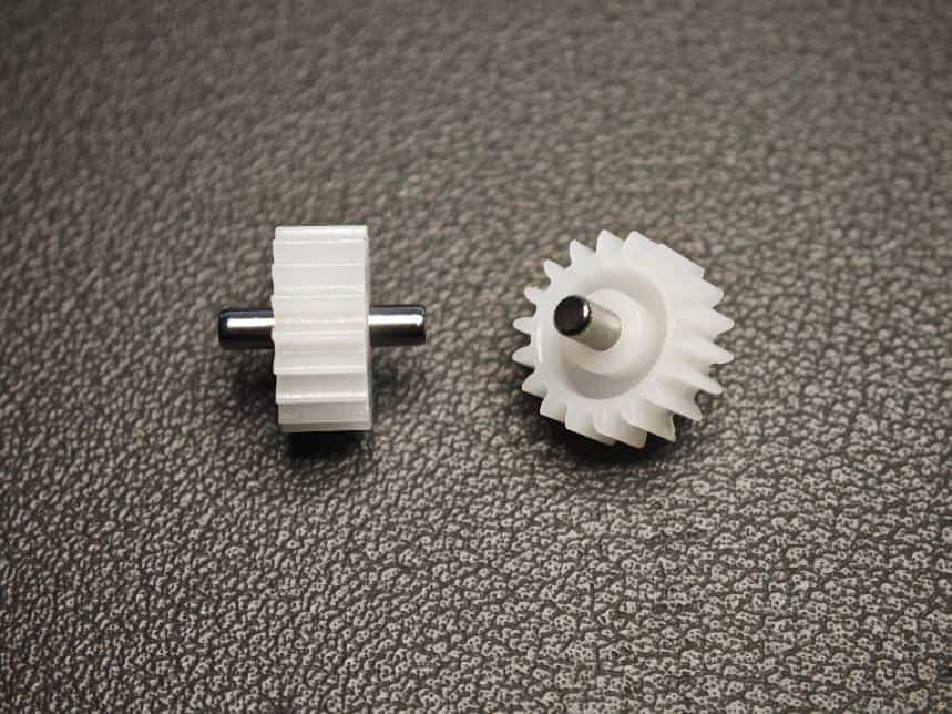
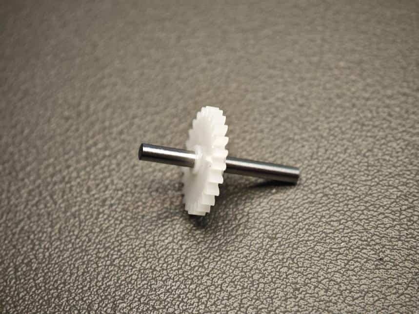
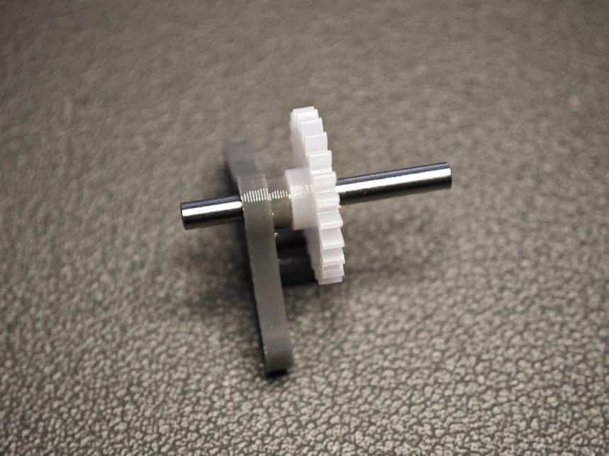
- Take the large gear (242A) and long shaft (2×20mm). Assemble as shown (one end should be flush with the arrow).
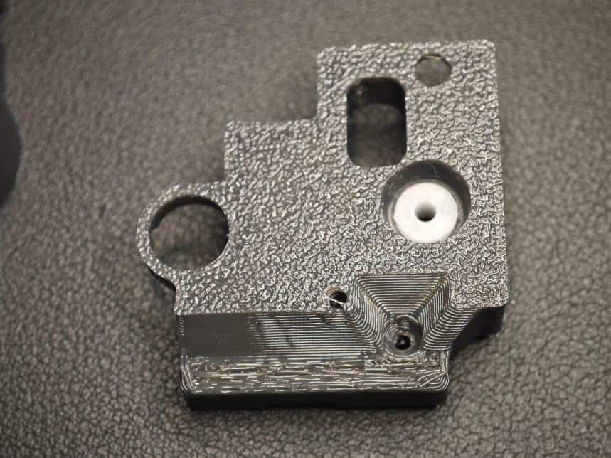
- Take the two triangular parts (replaceable).
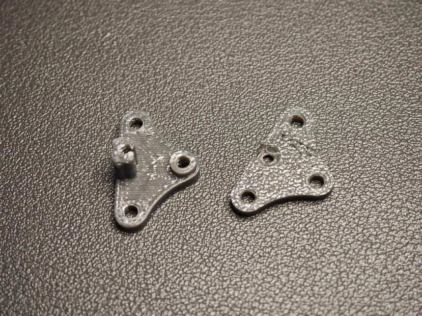
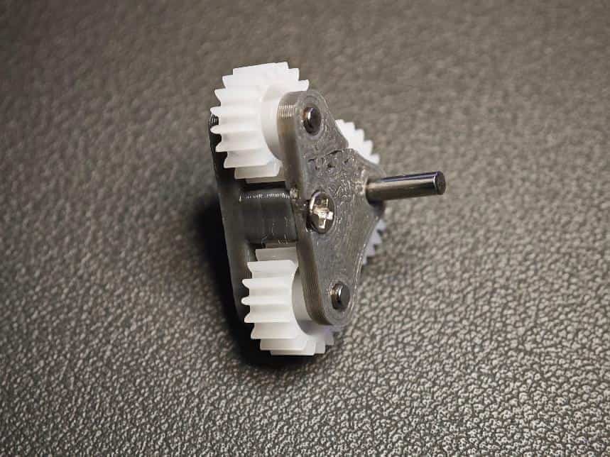
- Assemble the large gear and triangular parts (!!! Pay attention to gear orientation!!!).
- Assemble the remaining two small gears, cover the assembly, and tighten the screws (M2×8 self-tapping). The gears should rotate smoothly—neither too loose nor too tight.
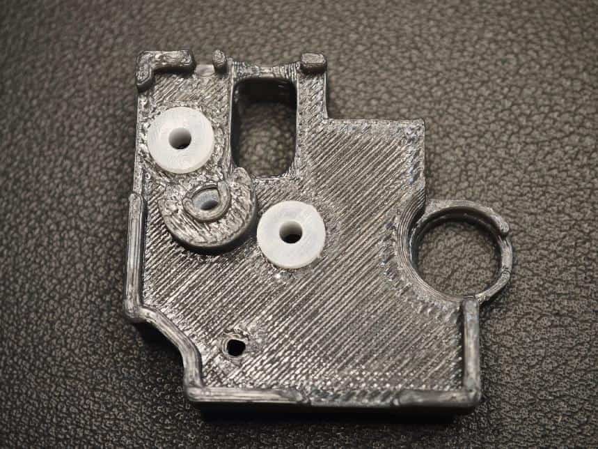
- Insert five 62B bushings (white) into the base and top cover as shown. Press firmly.
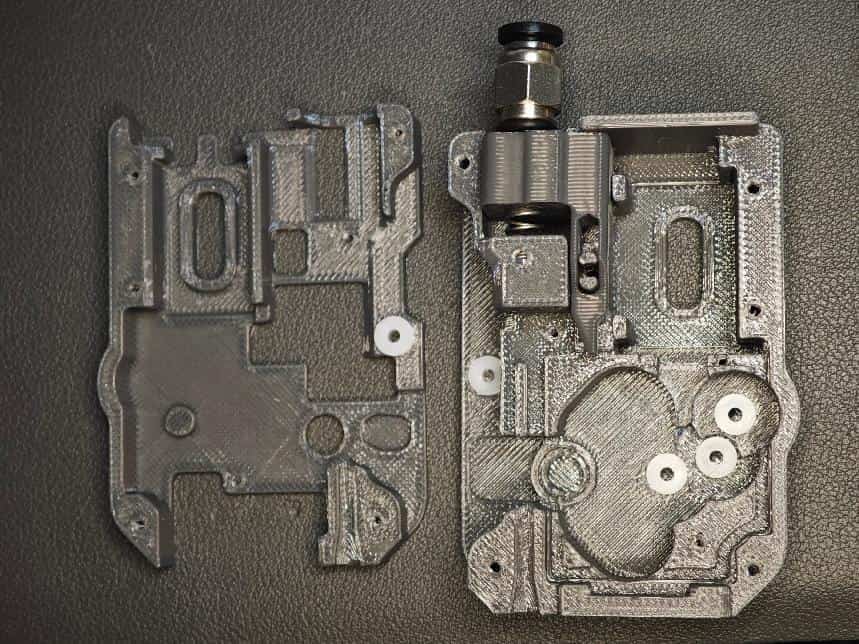
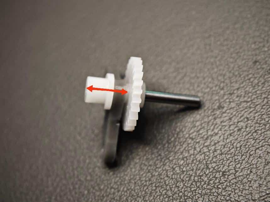
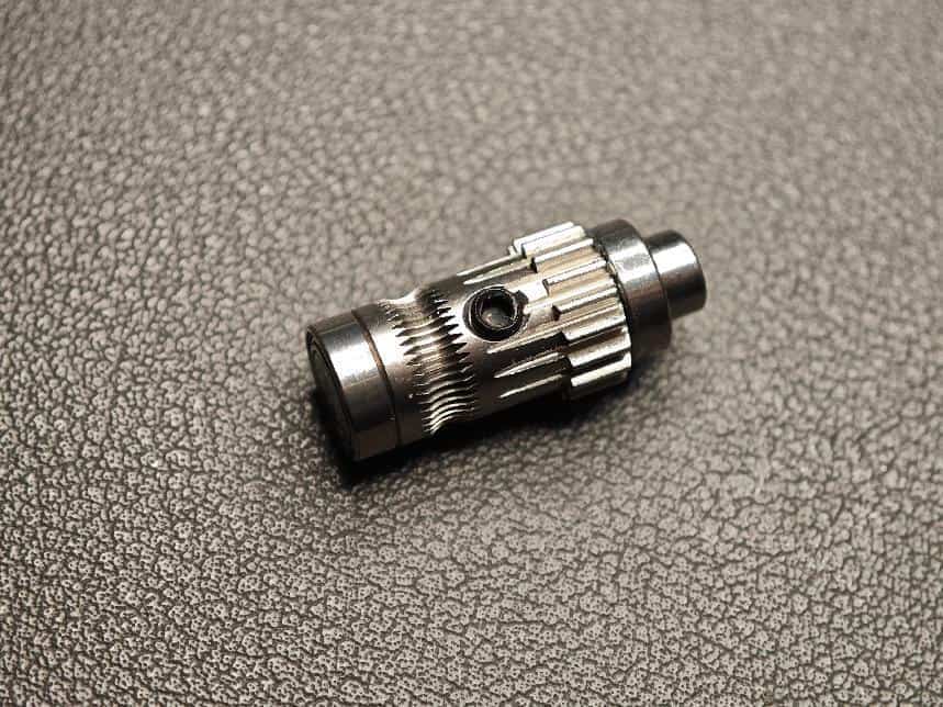
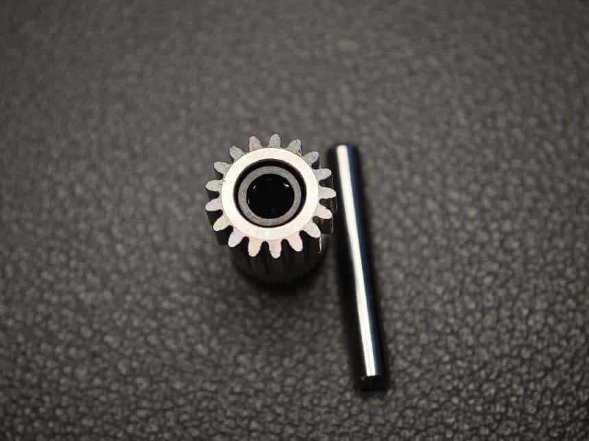
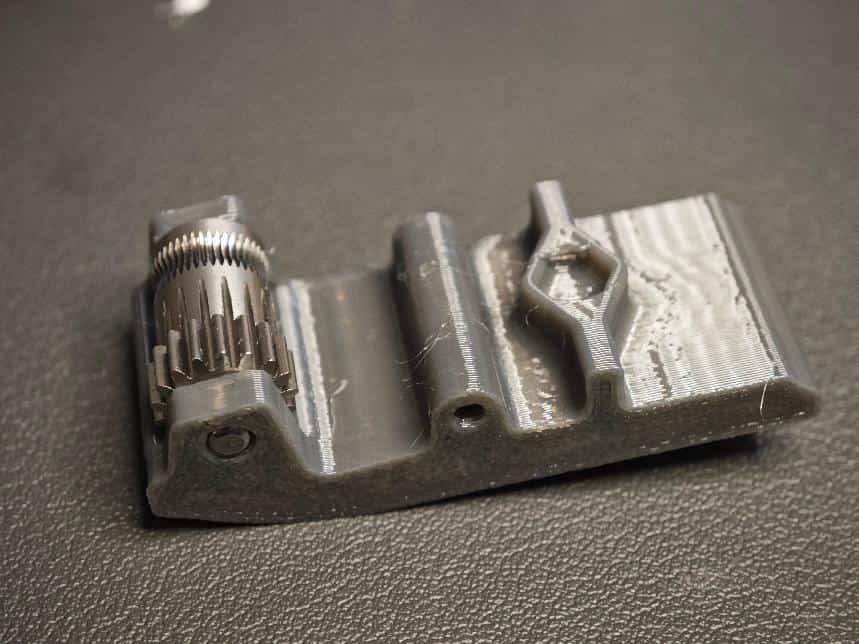
- Assemble the BMG extruder mechanism. Prepare the threaded extruder gear, set screw, one thick shaft (5×22mm), and two bearings (MR85ZZ).
WARNING
The shaft tolerance may be poor. Select shafts with correct dimensions to avoid issues like bearings not fitting or magnets not rotating.
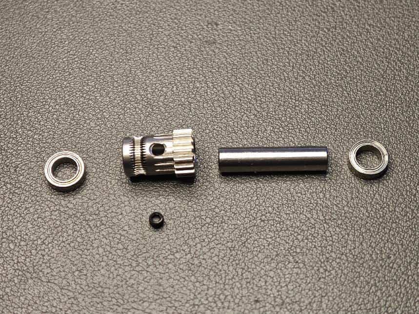
- Assemble as shown (note orientation). One end of the shaft must be flush with the bearing (for magnet placement). Ensure the set screw is tightened (protrusion is acceptable unless it interferes with gear operation).
- Insert the extruder assembly into the base shell.
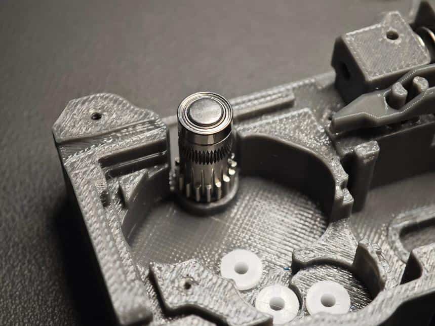
- Place the gear assembly into the bushings with the screw side facing down.
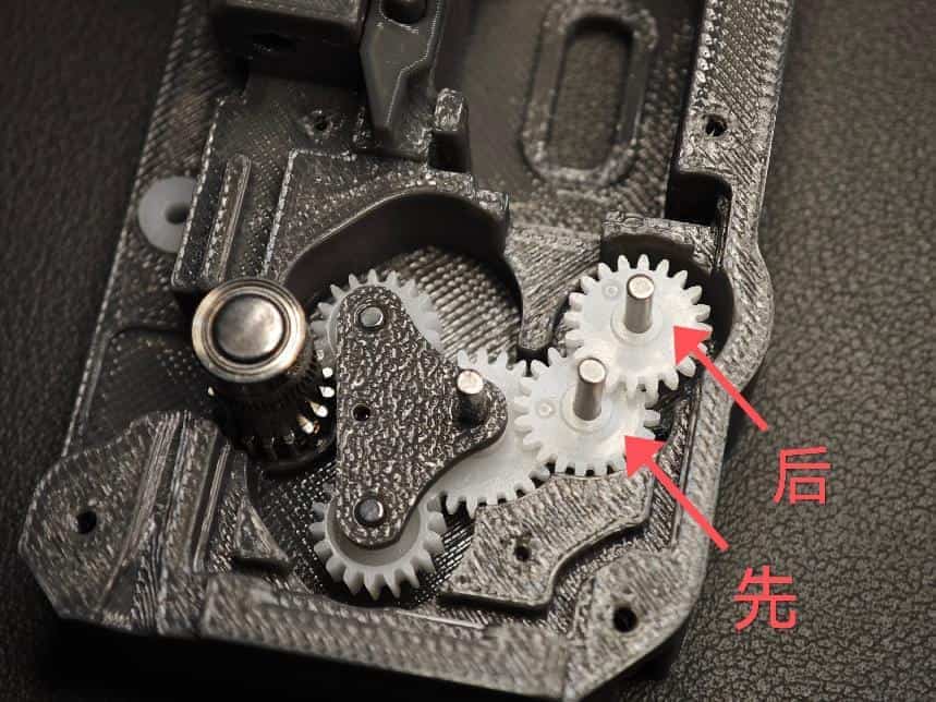
- Insert two long shafts (2×20mm) into the 62B bushings. Install two gears (20082B double-layer spur gears) in order.
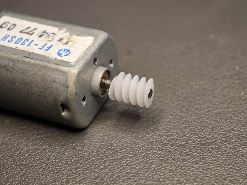
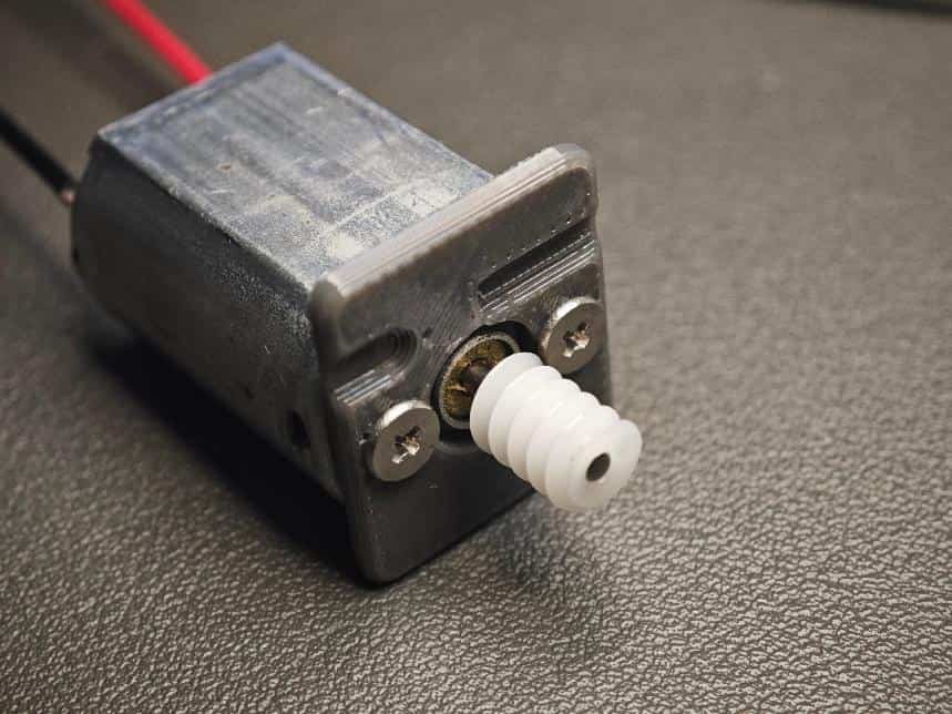
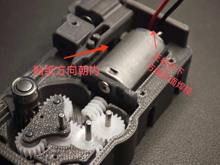
- Combine the FF-130SH motor with the worm gear (682A). Ensure alignment to avoid jamming.
- Insert the 62B bushing (white part) into the cover hole.
- Attach the motor cover and secure with two M2×4mm flat-head screws.
- Solder the motor wires (red dot indicates positive).
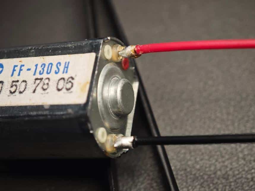
- Insert the motor into the slot (test motor rotation at 3V-12V to ensure gear engagement before proceeding).
- Attach the cover and secure with M2×8 screws. Apply grease to gears if needed.
- Install the photoelectric sensor module (choose the most stable variant; if all work, use the one labeled "7.2").
- Thread the motor wires through the top cover slot and close the cover.
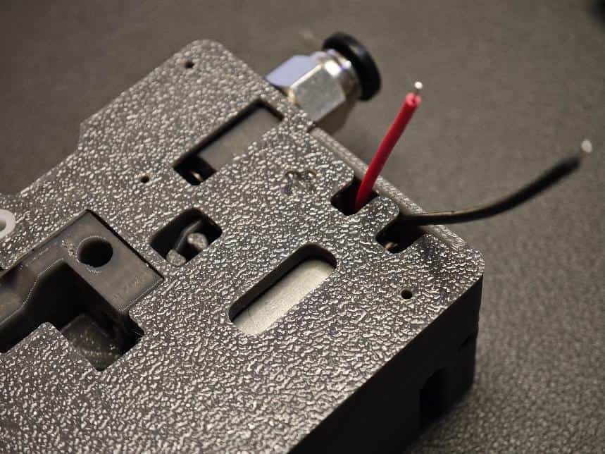
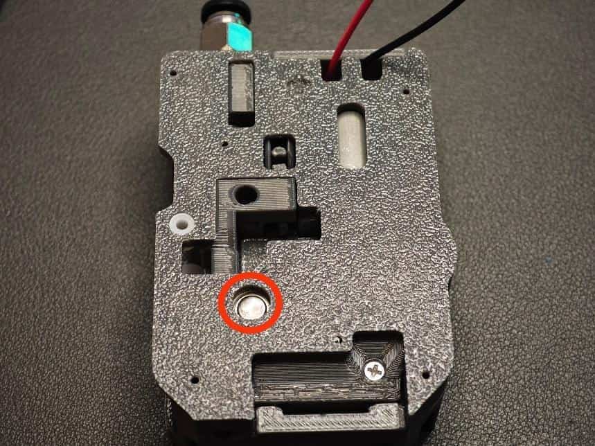
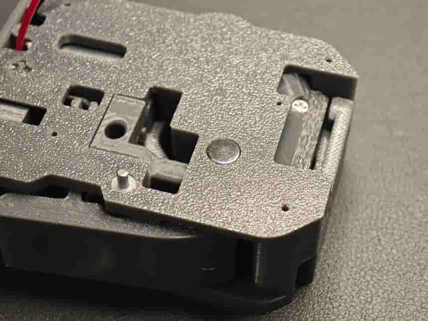
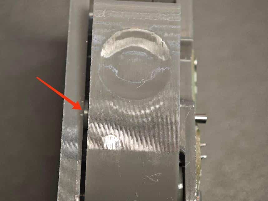
- Insert the radial magnet (6×2.5mm, critical—must be the correct size and type) into the marked hole. Ensure smooth rotation and flush fit.
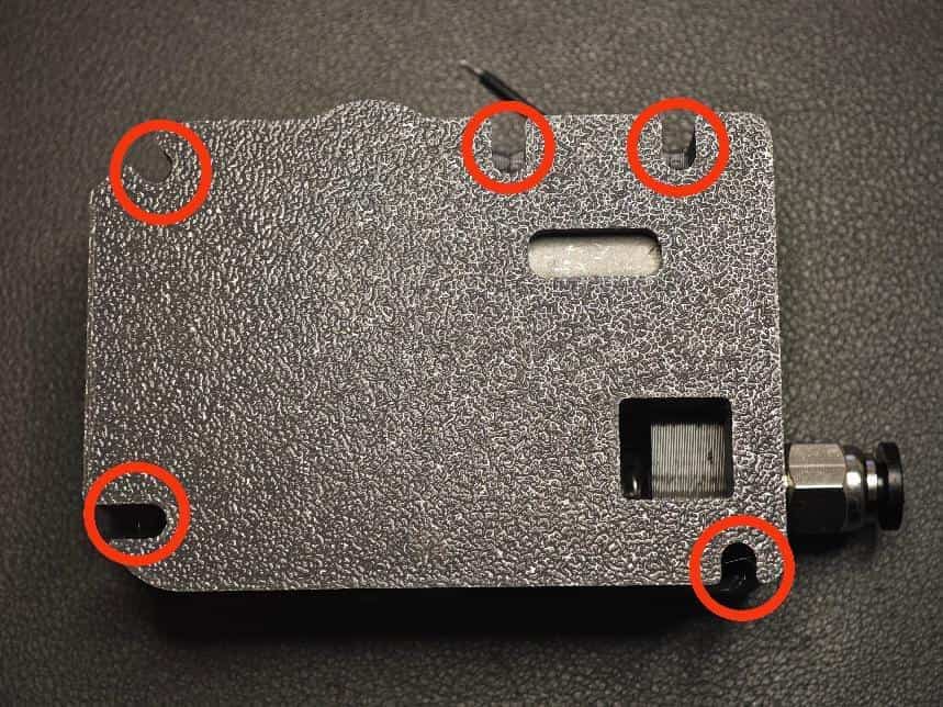
- Secure the back cover with five M2×8 self-tapping screws.
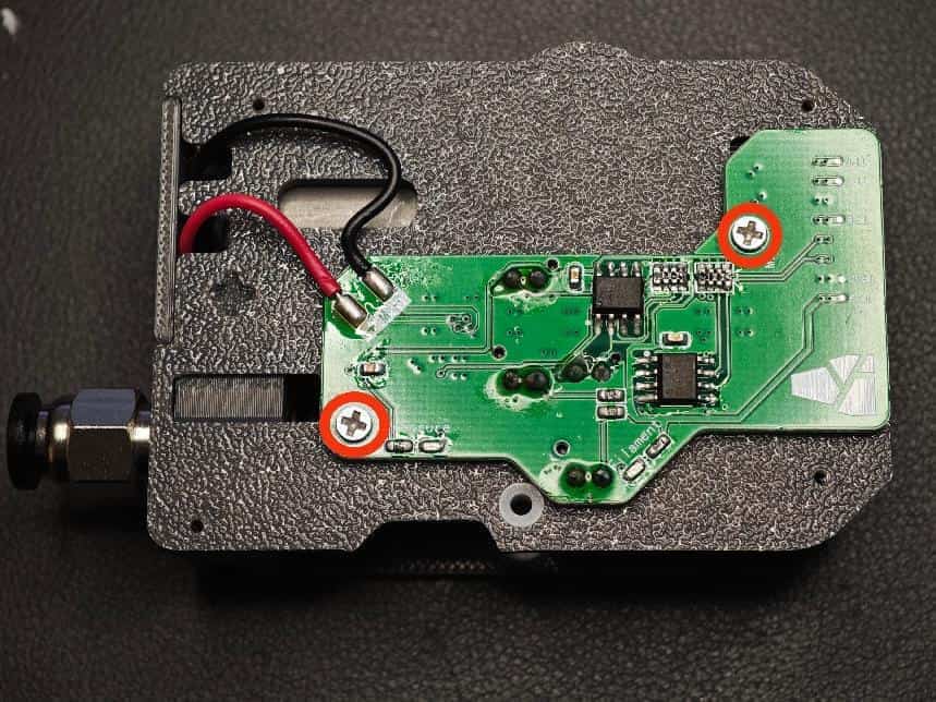
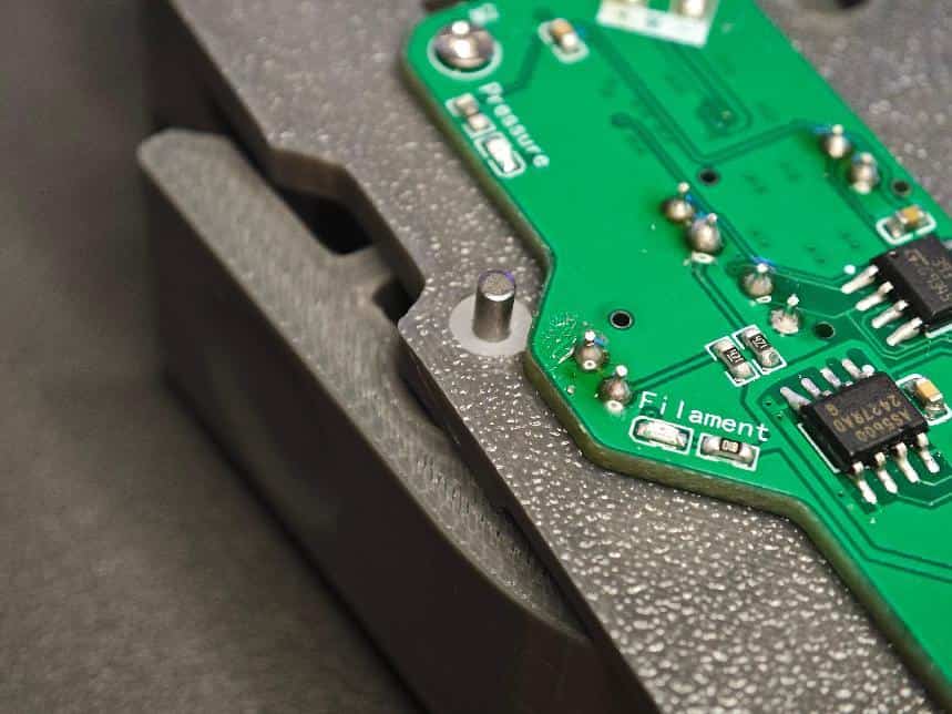
- Install the sub-board. Solder the motor wires (note polarity) and secure with two M2×8 screws.
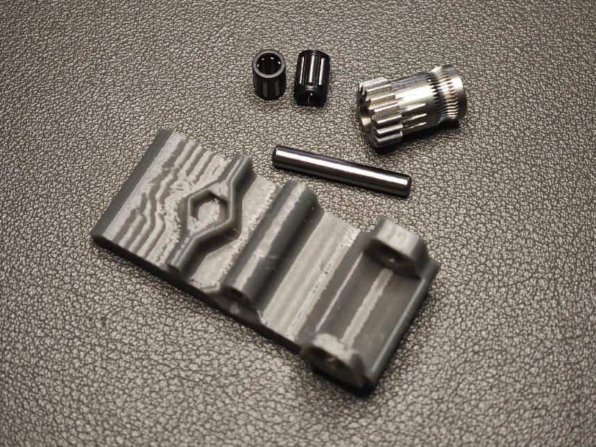
- Prepare the following parts: two needle bearings, BMG shaft, non-threaded spool gear, and printed wrench. Assemble as shown.
- Place the small spring (0.6×4×10mm) as shown. Attach the wrench and ensure the spring is seated correctly.
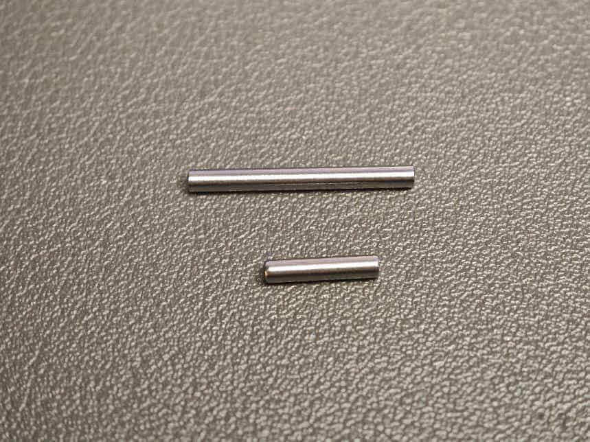
- Insert the short shaft (D2×10mm) and long shaft (D2×20mm) in order through the bushings and wrench hole. Ensure smooth rotation.
- Organize the motor wires, attach the cover, and secure with four M2×8 screws. The extruder assembly is now complete.
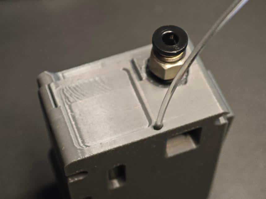
- Insert a transparent filament into the marked hole (push fully) and trim. This guides the LED light.
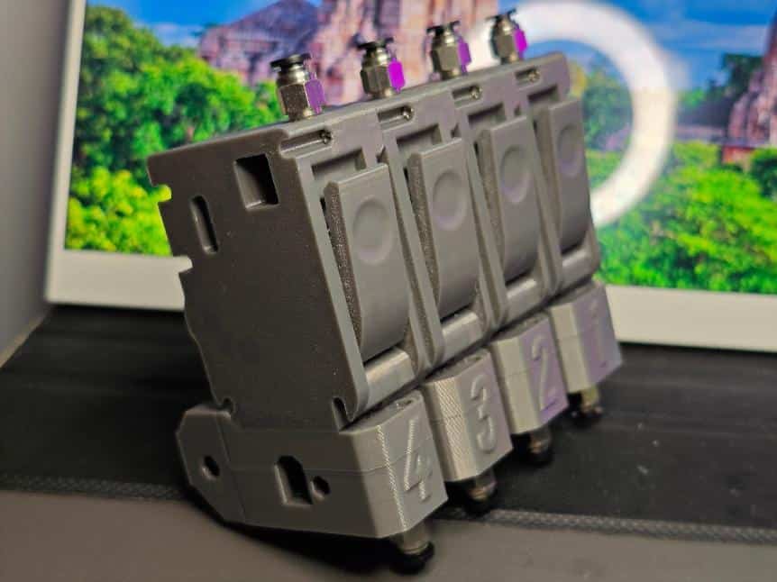
Repeat the above steps to assemble all four feeder units.
Step 2: Mechanical Assembly Part 2 (Base Installation and Connection)
- Connect the feeder units with PH2.0 10-pin male-to-male reverse cables (recommended length: 80mm).
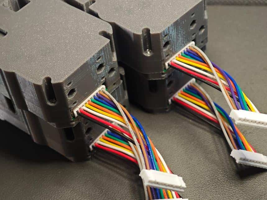
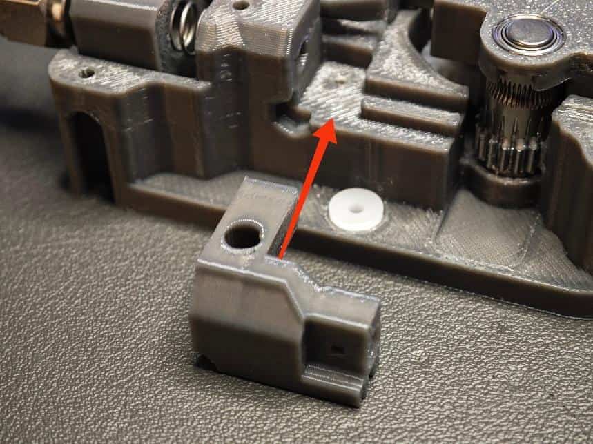
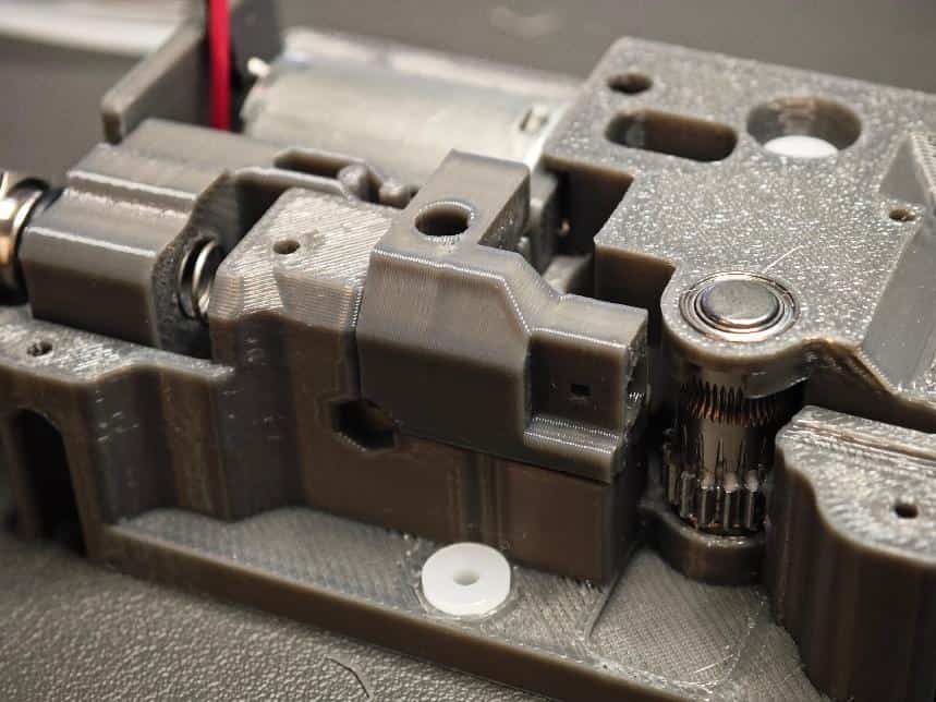
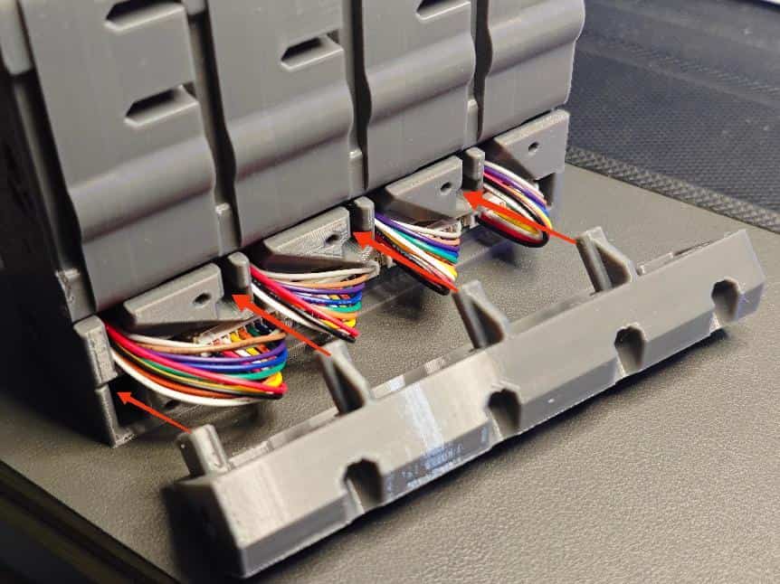
- Mount the feeder units onto the base cover. Align the holes and route the cables through the channels.
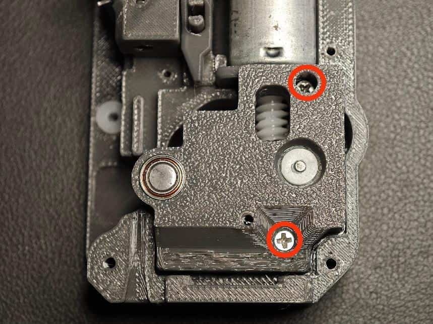
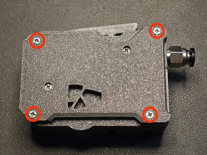
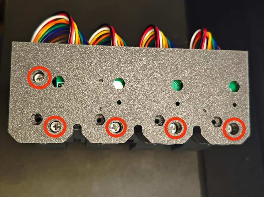
- Secure the base cover with M2×8 screws at the marked positions. Repeat for all feeders.
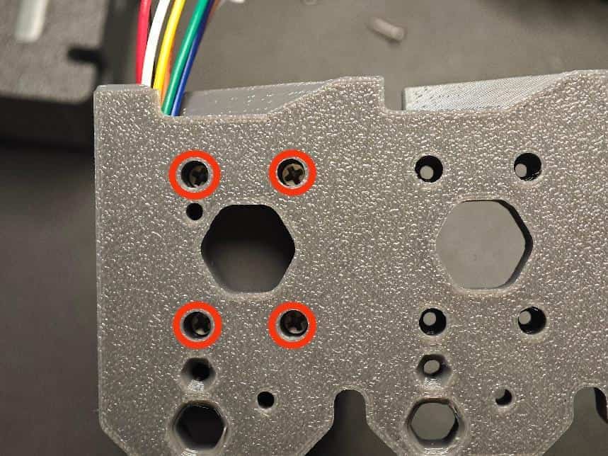
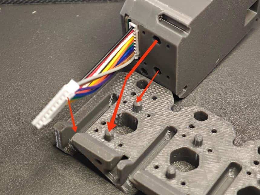
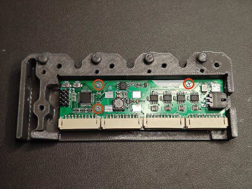
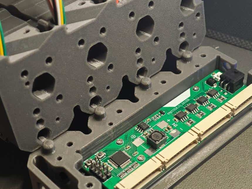
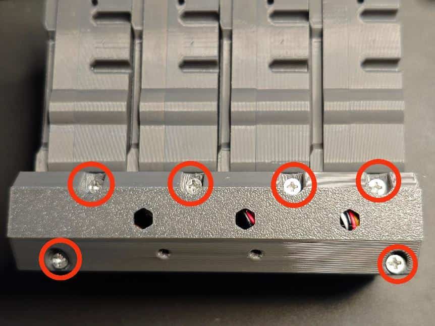
- Mount the mainboard onto the base. Secure with M2×8 screws at the marked positions.
- Assemble the base halves. Secure the bottom with M3×14 screws at the marked positions.
- Connect the cables to the ports, cover the cable compartment, and secure with M3×14 screws.
- Attach pneumatic fittings (PC4-M6 passthrough) to the four bottom feed ports.
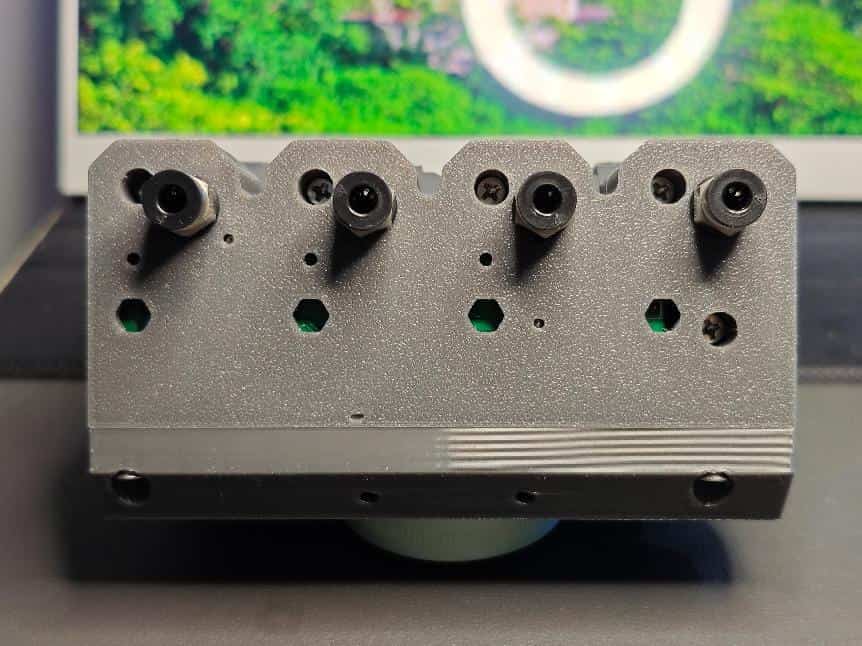
- The BMCU assembly is now complete.
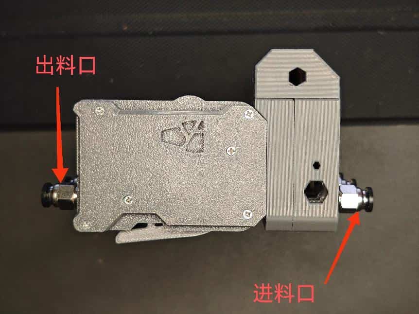
- The feed and output ports are oriented as shown. Do not reverse them.
3D Printer Connection Guide
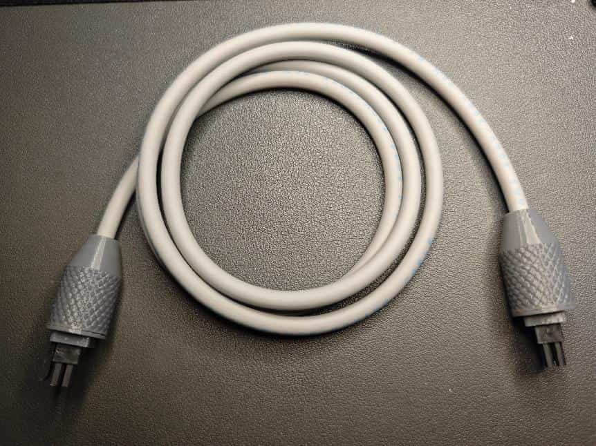
Use a 1-meter male-to-male reverse MX3 cable. Custom lengths are possible. You can buy pre-made cables (see the materials list) or DIY.
DIY Cable Guide:
- Materials: 1-meter 4-core 0.3mm² cable (or similar 5.2mm OD), 8x MX3.0 pins, 2x MX3.0 male housings, 2x 3D-printed strain reliefs (recommended model: https://makerworld.com.cn/models/846836).
- Tools: SN-58B crimper, wire stripper, etc.
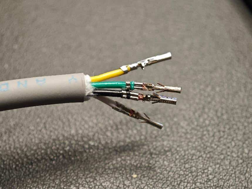
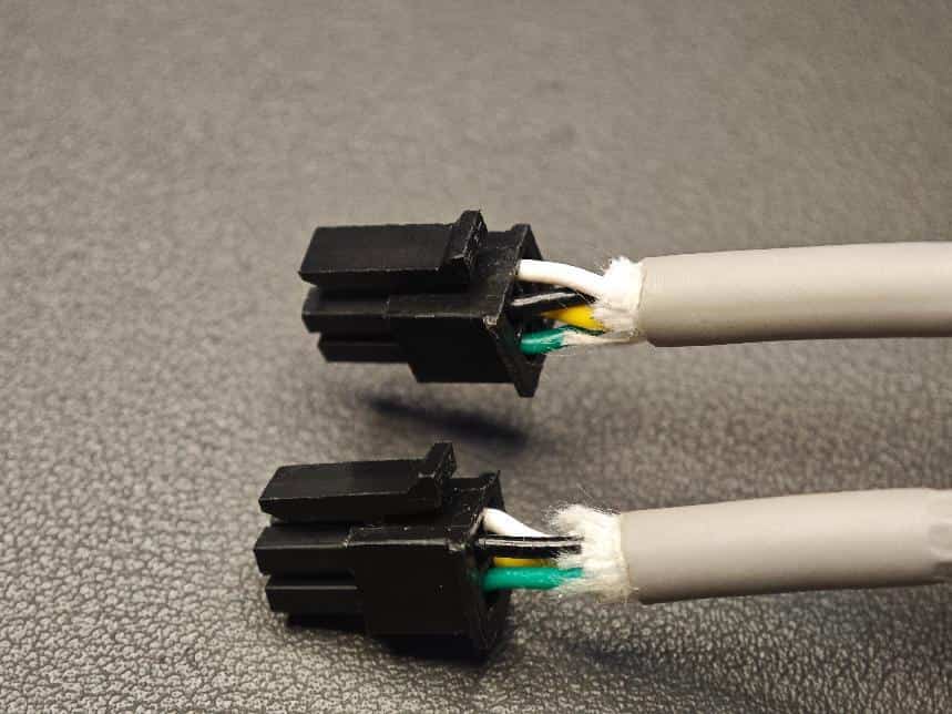
- Strip 12mm of outer insulation and remove filler threads.
- Strip 3mm of inner insulation.
- Crimp the pins (refer to online tutorials).
- Thread the cable through the strain relief parts.
- Insert the pins into the MX3.0 housing in the correct order (!!! critical to avoid damage !!!). Attach the strain relief.
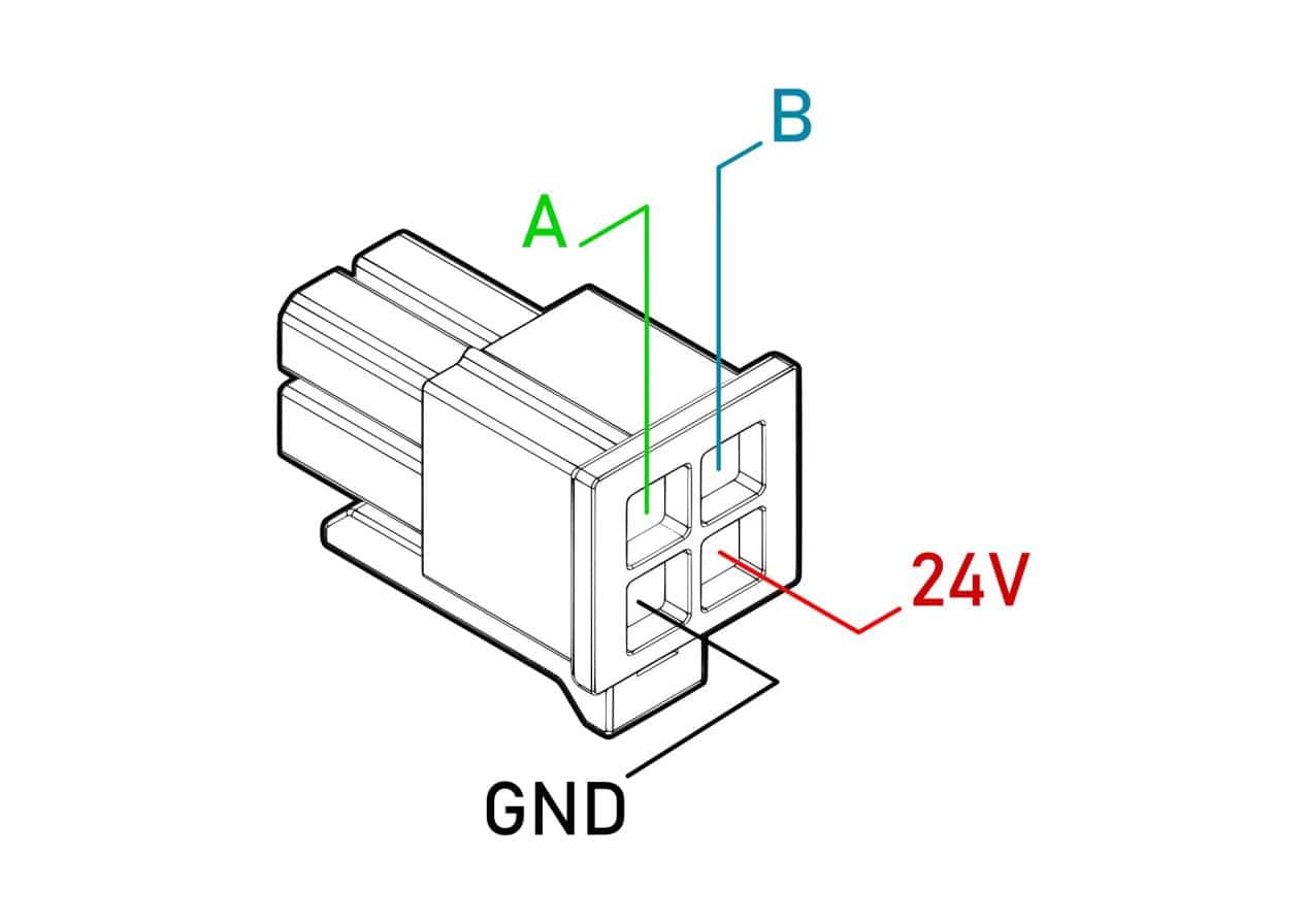
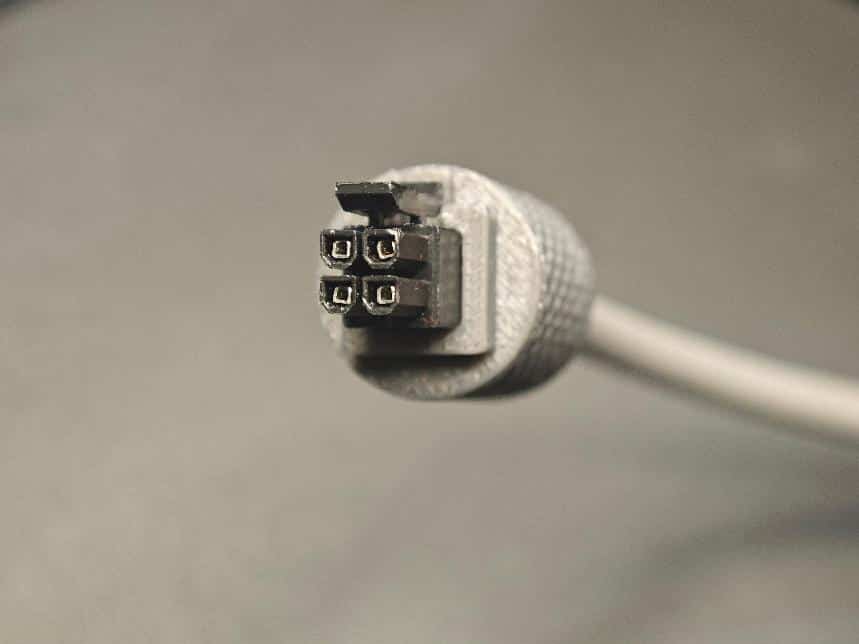
- Repeat steps 6-7 for the other end. Both ends must have the same pinout.
Mounting Bracket Options
No fixed tutorial. Many Bambu Lab-compatible bracket models are available online. Choose one that suits your needs.
Troubleshooting
Printer does not recognize BMCU (AMS not displayed), mainboard shows red LED
Solution: Usually caused by reversed A/B wires in the cable. Swap them. If unresolved, check for soldering issues (cold joints, bridges) or faulty communication components (e.g., incorrectly oriented or poorly soldered chips). If using a DC-DC module, voltage instability may be the cause.
Filament detected when none is present, or sensor LED flickers
Solution: Often due to misaligned sensor holes in the original shell model, loose feed channels, or poorly soldered sensors. Use the improved shell with replaceable sensor modules or resolder the sensor.
Filament feeds then retracts, failing to load
Solution: Common causes: missing radial magnet, magnet stuck, missing extruder gear set screw, incorrect magnet type/size (must be 6×2.5mm radial magnet). Test by rotating two magnets 180°—they should repel. Alternatively, check for AS5600 encoder soldering errors or gear jams causing step loss.

Flashing fails—device not recognized (no COM port)
Solution: Usually due to a short (3.3V to GND), incorrect wiring, or driver issues (rare—most USB-TTL adapters auto-install drivers).
Flashing fails—protection removal or download fails, or software does not detect COM port
Solution: Often caused by incorrectly oriented or poorly soldered MCU, wrong wiring, or incompatible flasher (older models may not work with newer Windows versions). For USB-C boards, retry protection removal twice.
Feeder motor spins but does not feed/retract, or gears do not turn when they should
Solution: Usually due to loose/faulty triangular clutch gears or shell misalignment causing gear binding.
wanzi's note: See Troubleshooting for solutions.
Loud feeder noise
Solution: Often caused by misaligned worm gear (not flush with motor shaft), gear friction, or lack of lubrication (apply grease).
Filament inserted, sub-board LED on, but printer does not detect it
Solution: Often due to missing magnet (requires power cycle—avoid hot-plugging). Press the mainboard R button or check for loose PH2.0 connectors/cable breaks. Resolder if needed.
Sub-board LEDs malfunction without shell; or constant red LED when no filament is inserted
Solution: Often due to reversed resistors, incorrect PH2.0 male-to-male reverse 10-pin cables (80mm), loose connectors, or solder bridges (common near resistors/capacitors).
Filament inserted, sub-board LED off, but printer displays it
Solution: Usually caused by reversed LED polarity. Correct as shown:
Print stalls at 99%, endless retraction, or fails to auto-unload
Solution: Cause unclear (may be communication or hardware related). Manually unload the filament. Properly adjusting the triangular clutch gears and placing the BMCU sideways can reduce occurrences.