

Version 180 BMCU Assembly Guide
Note
This content was provided by community member @baixiaotao
Preparation of Materials (Excluding 3D Printed Files):
Version 180 is a modification based on version 130. The PCB is identical. Please refer to the version 130 guide for all PCB-related information.
Changes in the bill of materials are minimal and are only described here relative to version 130. For the full list, refer to the version 130 guide.
Changes in the bill of materials:
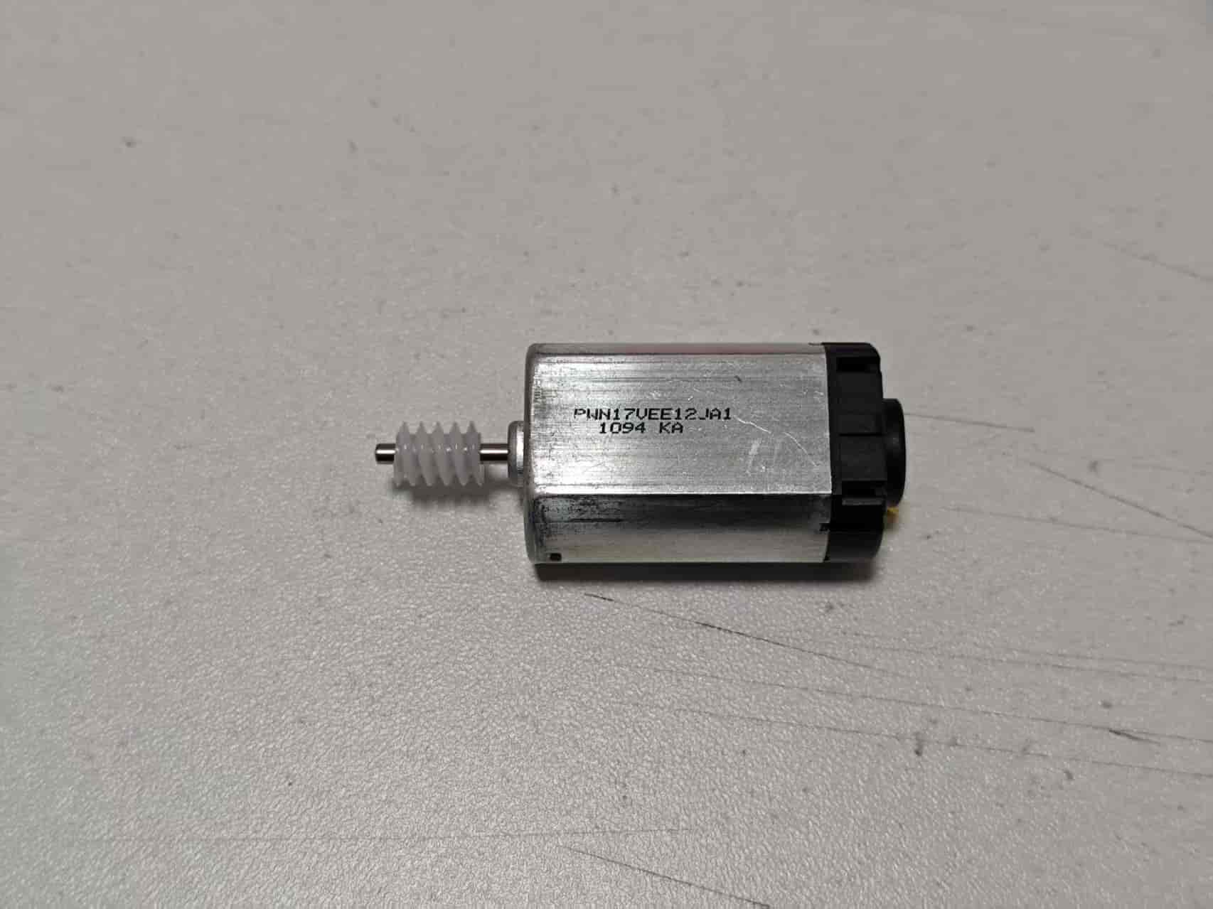
- The original 130 motor is replaced by a 180 motor. It is recommended to use a 180 motor with a shaft length of 10mm–12mm. Most 180 motors rated at 12V–24V should work. A total of 4 units are needed. Recommended models include:
- PWN17VEE12JA1 https://item.taobao.com/item.htm?_u=qu6u6p3c2bf&id=650572440927&spm=a1z09.2.0.0.7c412e8dH0f2vw (Price at the time of writing: 1.8 RMB)
- FK-180SH-12280 (has significantly increased in price)
- The buffer spring has been changed to a 0.5 x 6 x 15mm specification, 4 units needed. Purchase link: https://detail.tmall.com/item.htm?_u=qu6u6p36069&id=649882524891&spm=a1z09.2.0.0.4d042e8dhdKyYV&skuId=4728198936063
- Added a clutch spring, specification 0.4 x 3 x 5mm, 4 units needed. Purchase link: https://detail.tmall.com/item.htm?_u=qu6u6p36069&id=649882524891&skuId=4686949972659&spm=a1z09.2.0.0.4d042e8dhdKyYV
- M2x5 countersunk self-tapping screws are used in the 180 assembly guide. A total of 16 pieces are needed. If not purchased, M2x8 screws from the 130 guide can be used instead.
Enclosure 3D Print Files:
The enclosure has been fully redesigned and must be entirely reprinted.
The first version is only suitable for 180 motors with a full-metal back cover. If using the PWN17VEE12JA1 motor from the link above, print the second version.
If you have no special requirements or are unsure of the differences between the two versions, print the second version.
First version: https://makerworld.com/zh/models/1132822#profileId-1133350
The first version includes two print configurations. The first is a full set of component models, and 4 sets must be printed. The second configuration includes only "Clutch Part B - 4mm Thick 242A," which is for 4mm thick 242A gears. The product link lists the gear as 4mm thick, but the actual item is 3.2mm. If you truly have a 4mm 242A gear, use Clutch Part B from the second configuration.
Second version: https://makerworld.com/zh/models/1152568#profileId-1156984
The second version modifies the appearance and trims features that block the plastic rear cover of the 180 motor. It is compatible with both metal and plastic-backed 180 motors. The print configuration includes a full set of components and an installation aid.
In addition to the components, if this is your first time assembling a BMCU, you’ll also need the base and bracket. Please use the files from the group archive named "BMCU Integrated Package - V1.1".
Component Assembly:
The buffer lengths differ between the two versions. The second version has a larger motor mount. Otherwise, all else is the same. This guide uses the second version.
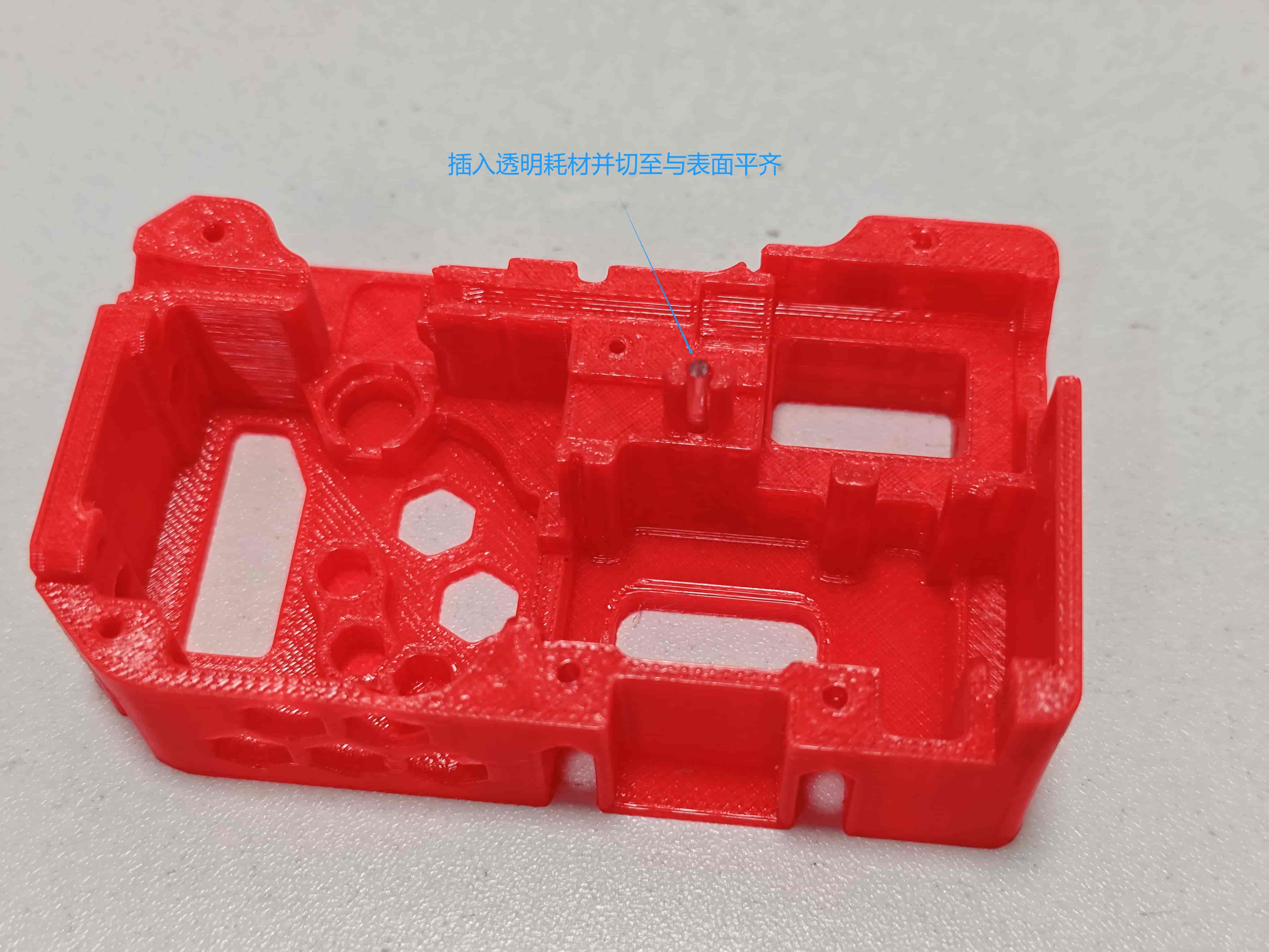
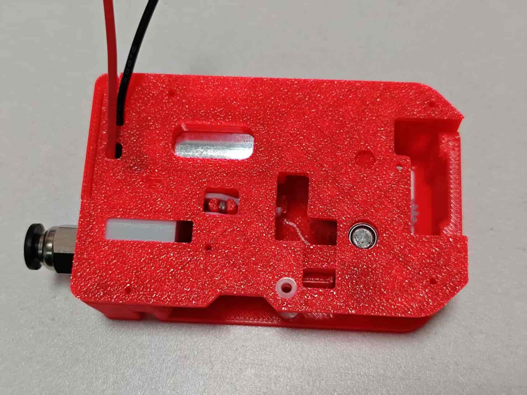
Take the bottom cover and insert a transparent filament into the LED hole. Then cut both ends of the filament flush with the bottom surface:
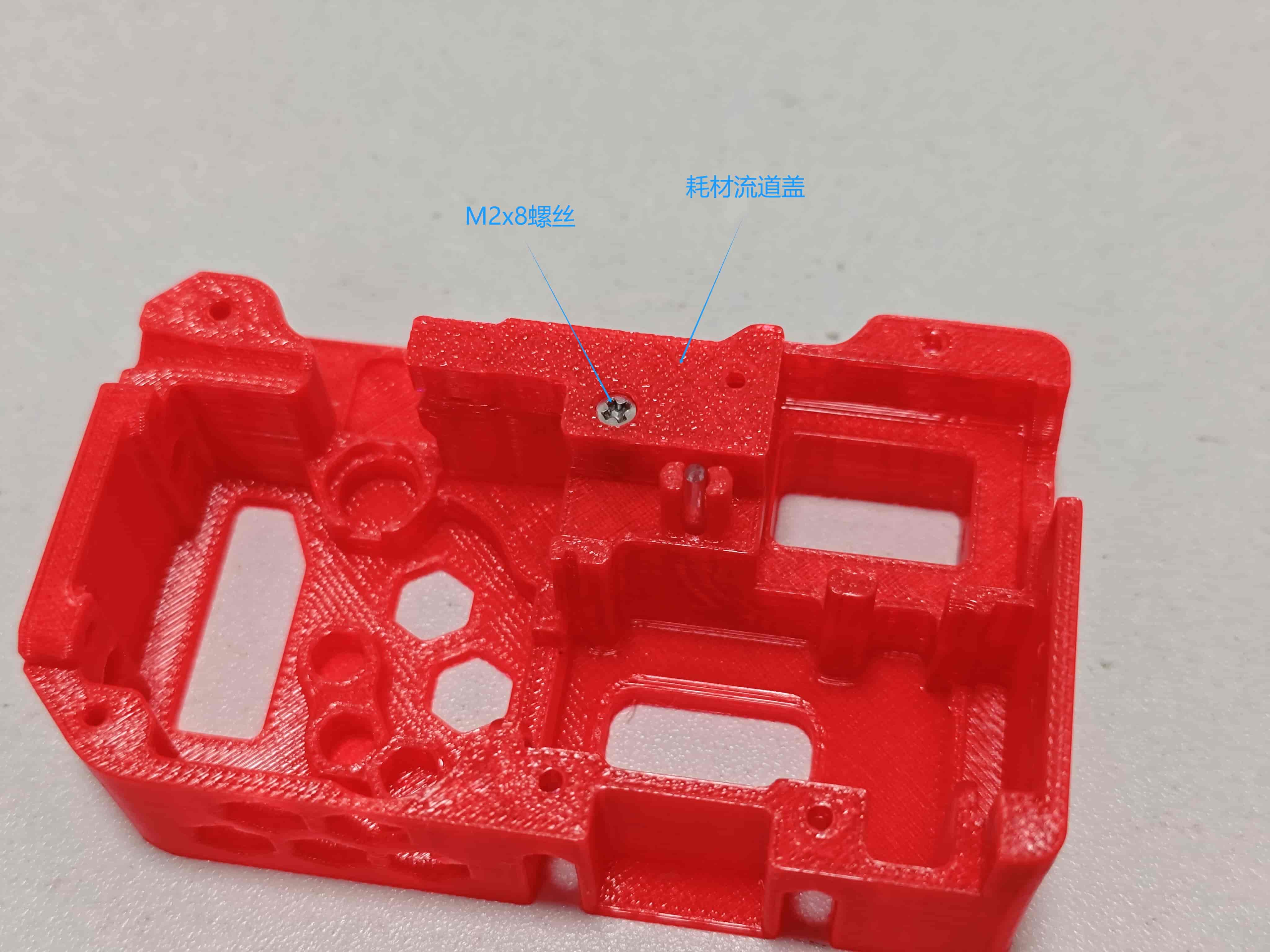
Take the filament channel cover and screw it into the bottom cover using M2 x 8 flat-head self-tapping screws:
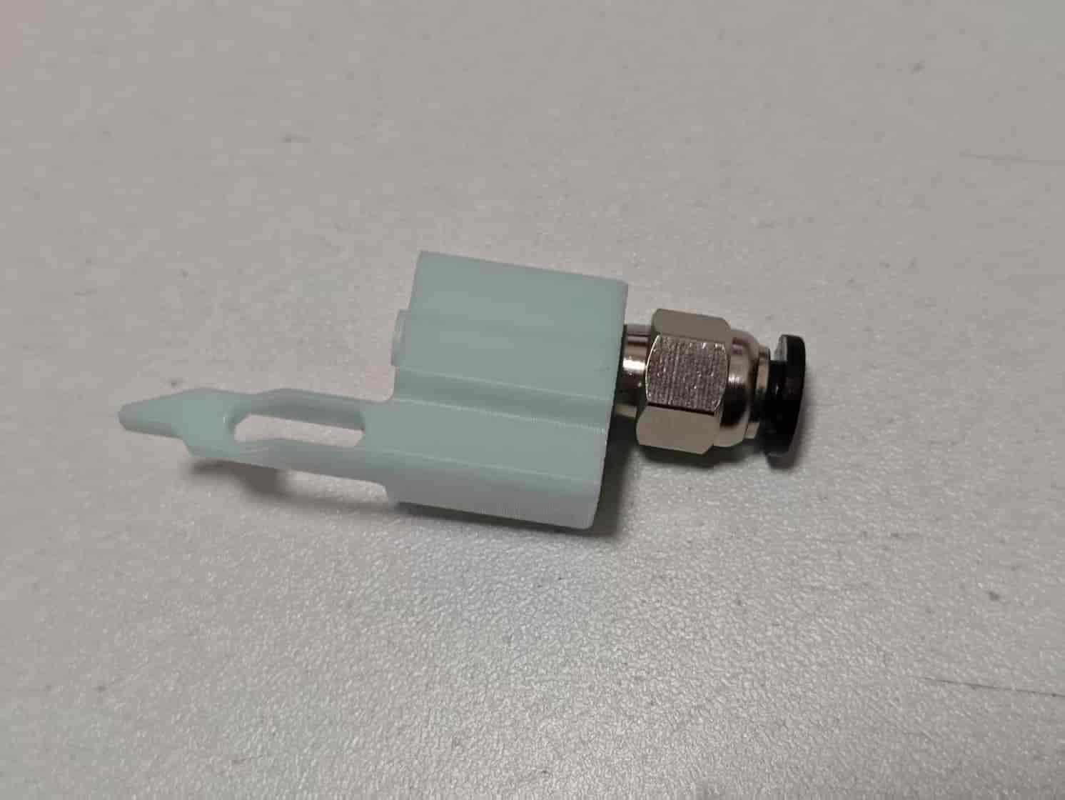
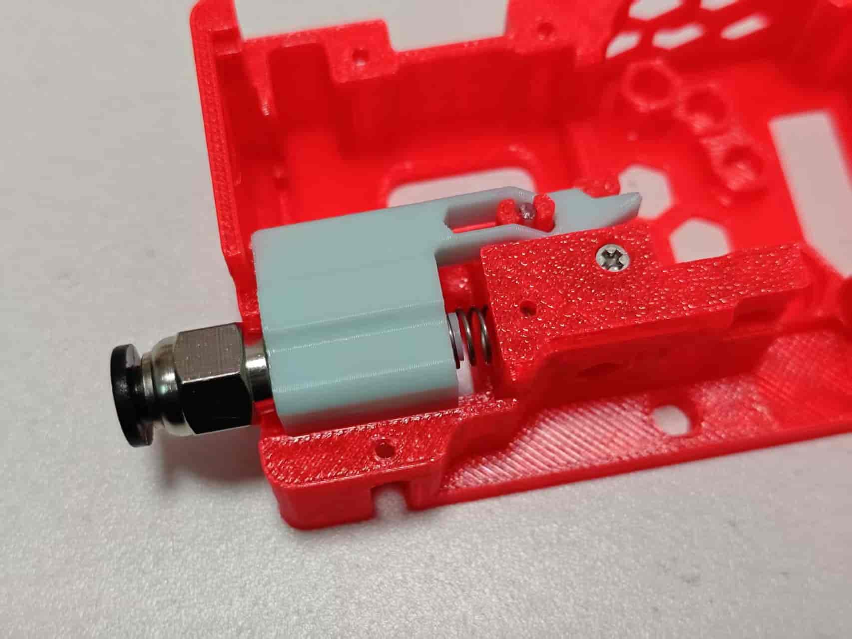
Screw the M6 pneumatic fitting into the buffer. The only difference between versions is buffer length:
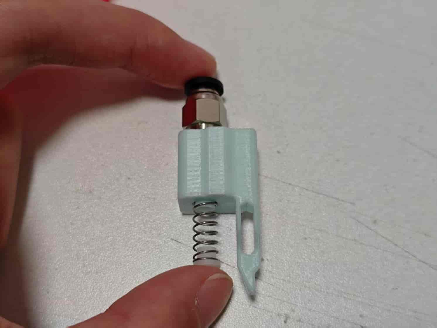
Place a 0.5x6x15mm spring on the buffer, then place a 62B bushing on top. Squeeze and install onto the bottom cover:
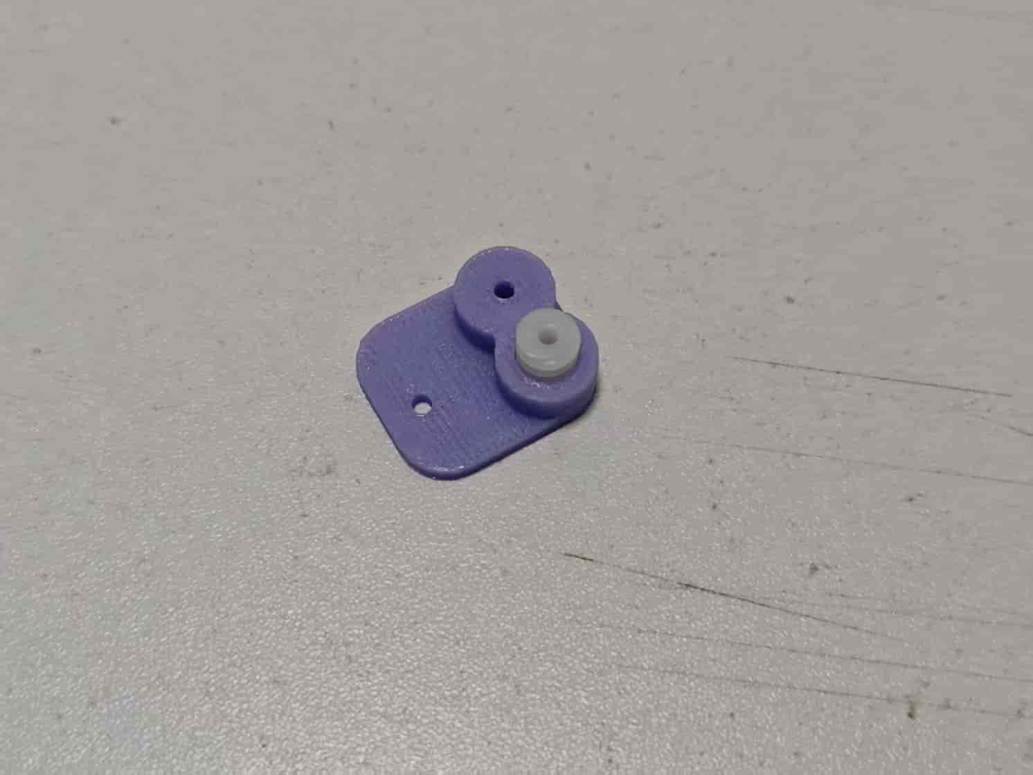
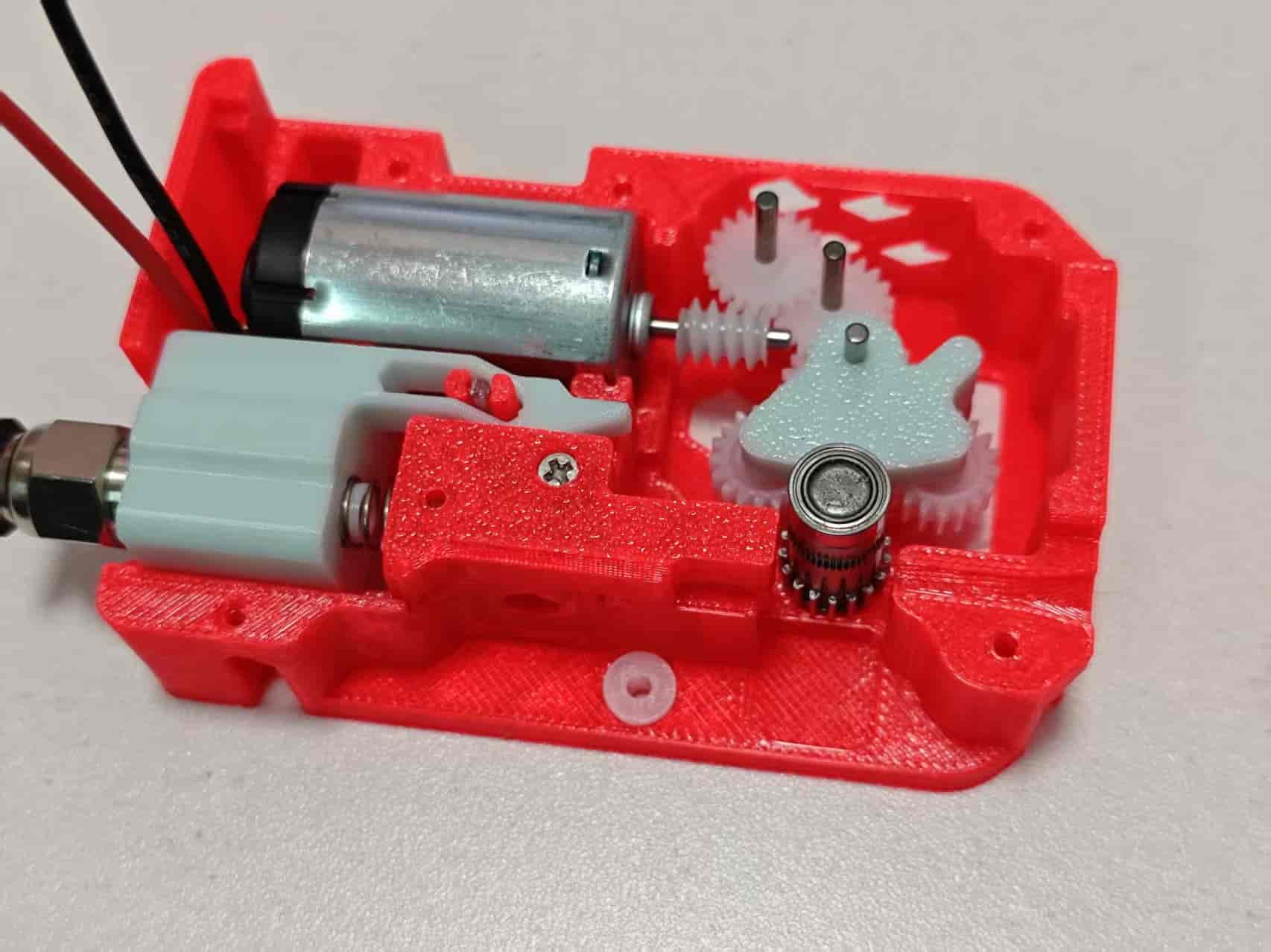
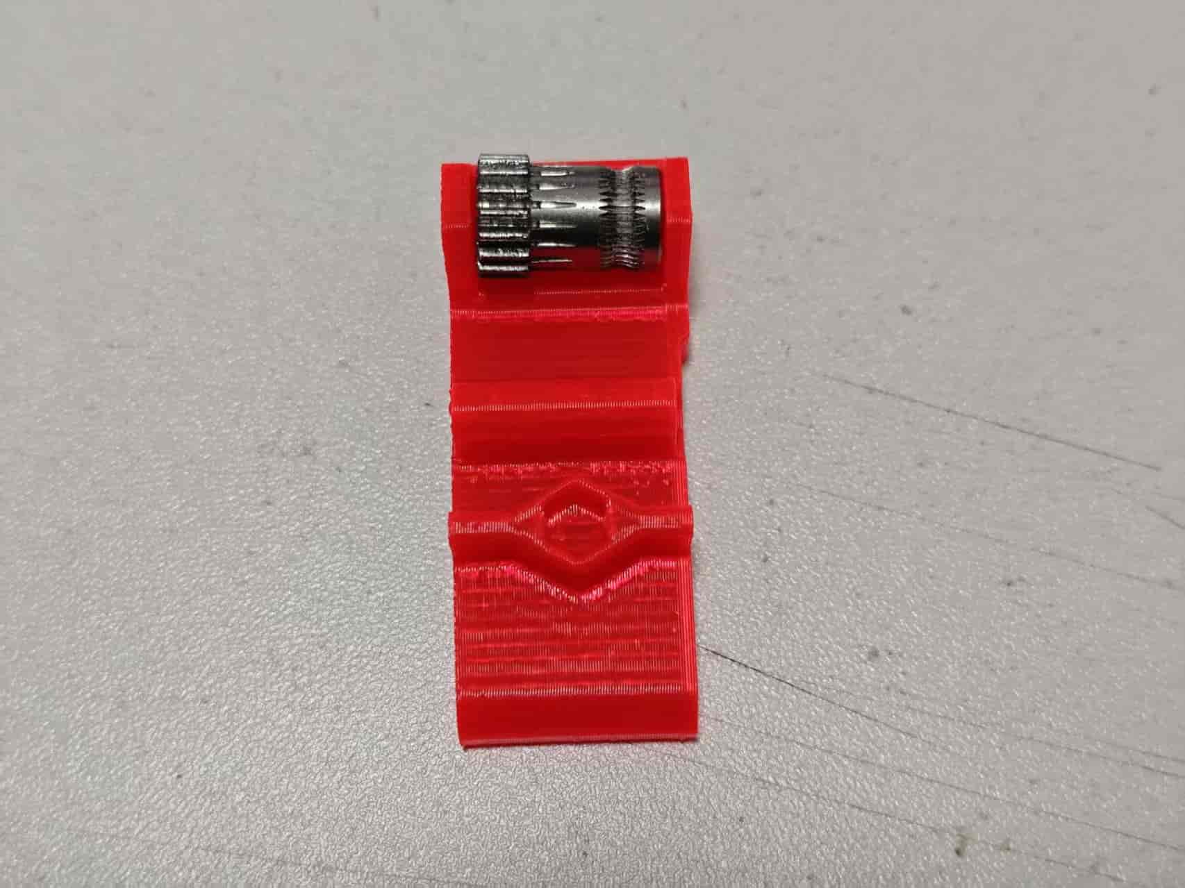
Place a 628 worm gear on the installation aid. Align the motor shaft with the worm gear hole and press down:
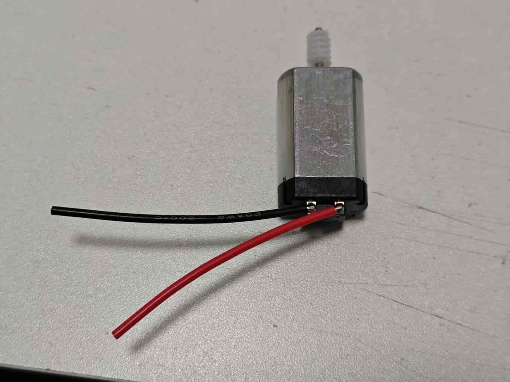
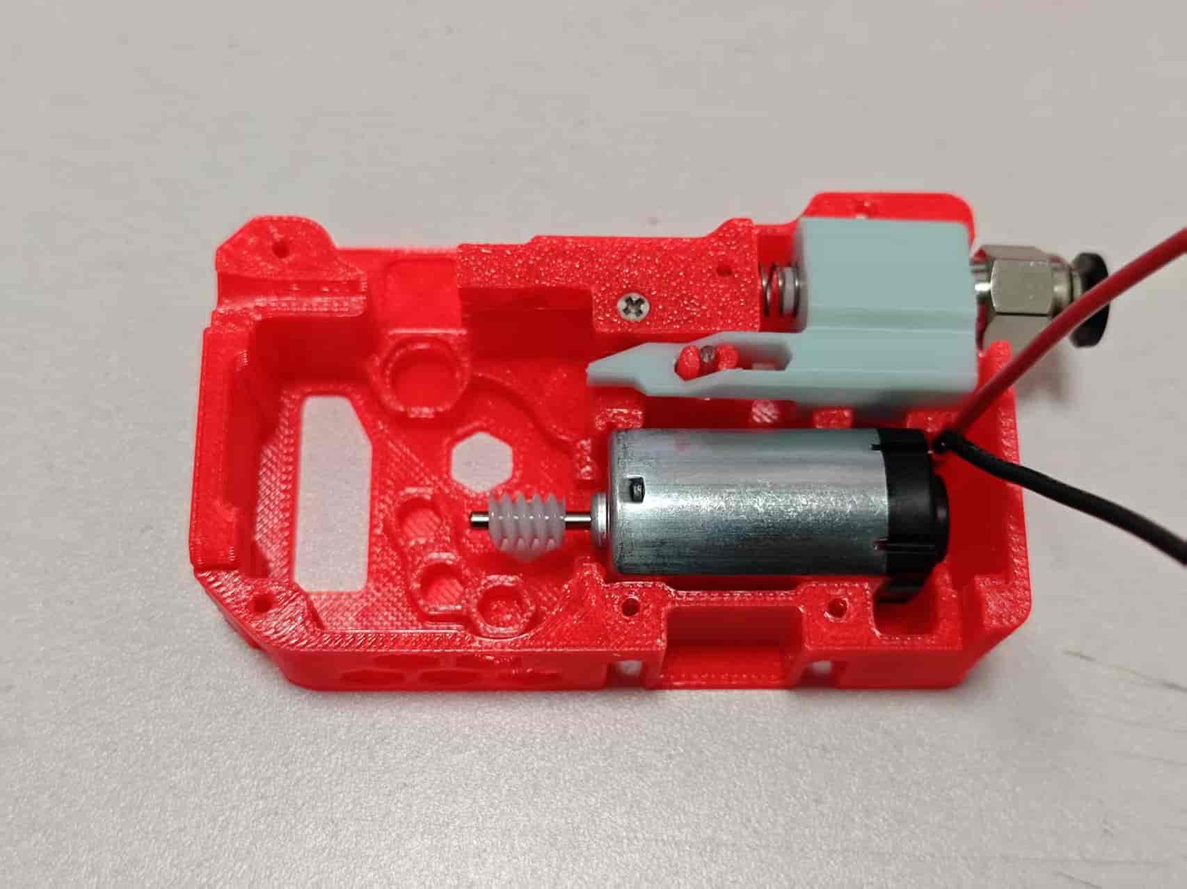
Solder wires to the motor. Recommended wire length: ~50mm. Pay attention to wire orientation!
After soldering, mount the entire motor assembly to the bottom cover:
Install four 62B bushings onto the bottom cover:
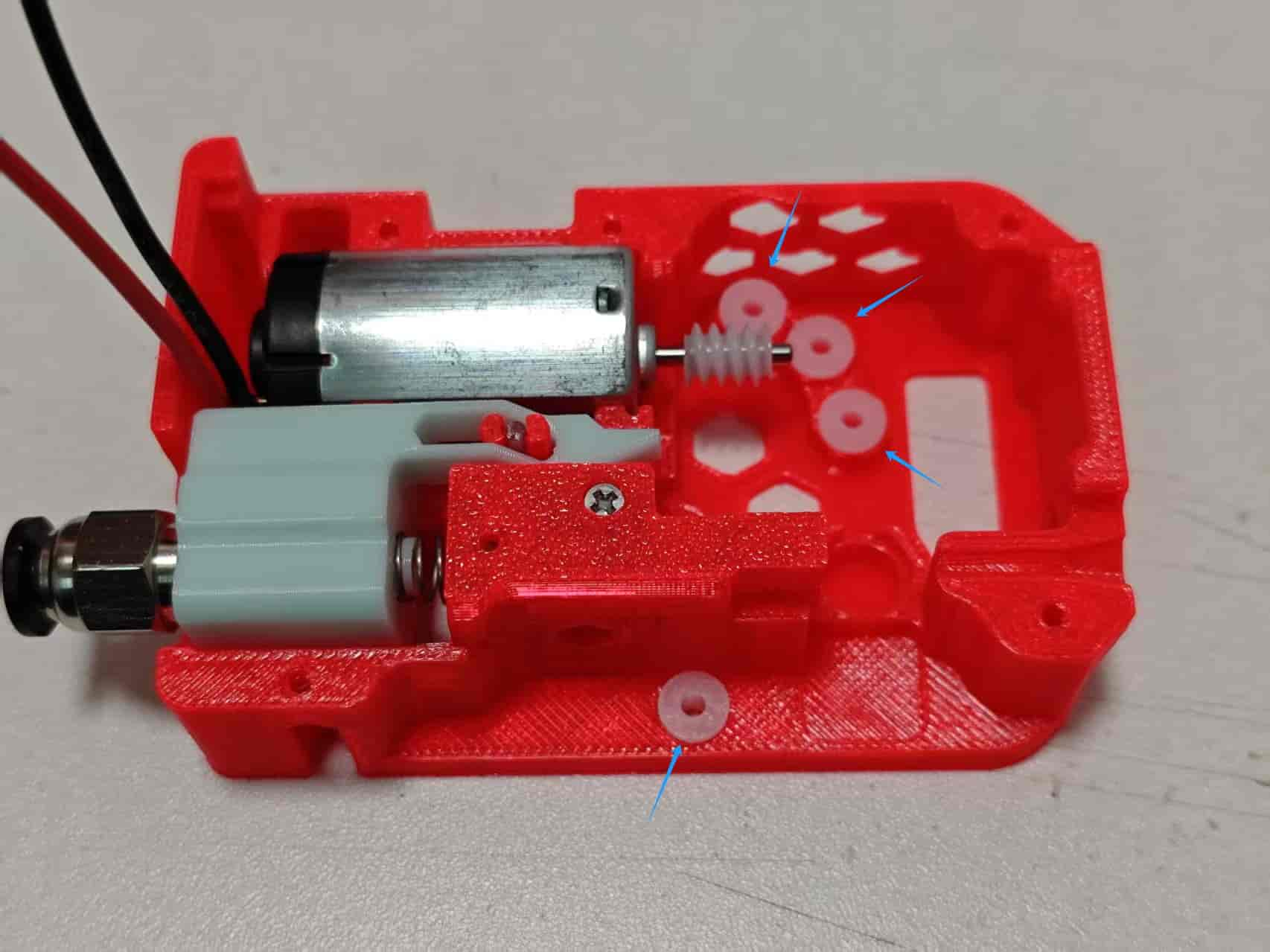
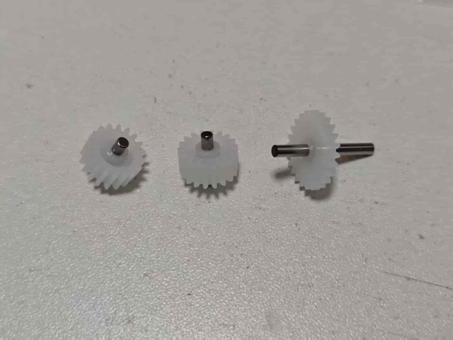
Take two 182A gears and two 2x6mm shafts. Assemble the gears in the center of the shafts. Use the installation aid if needed:
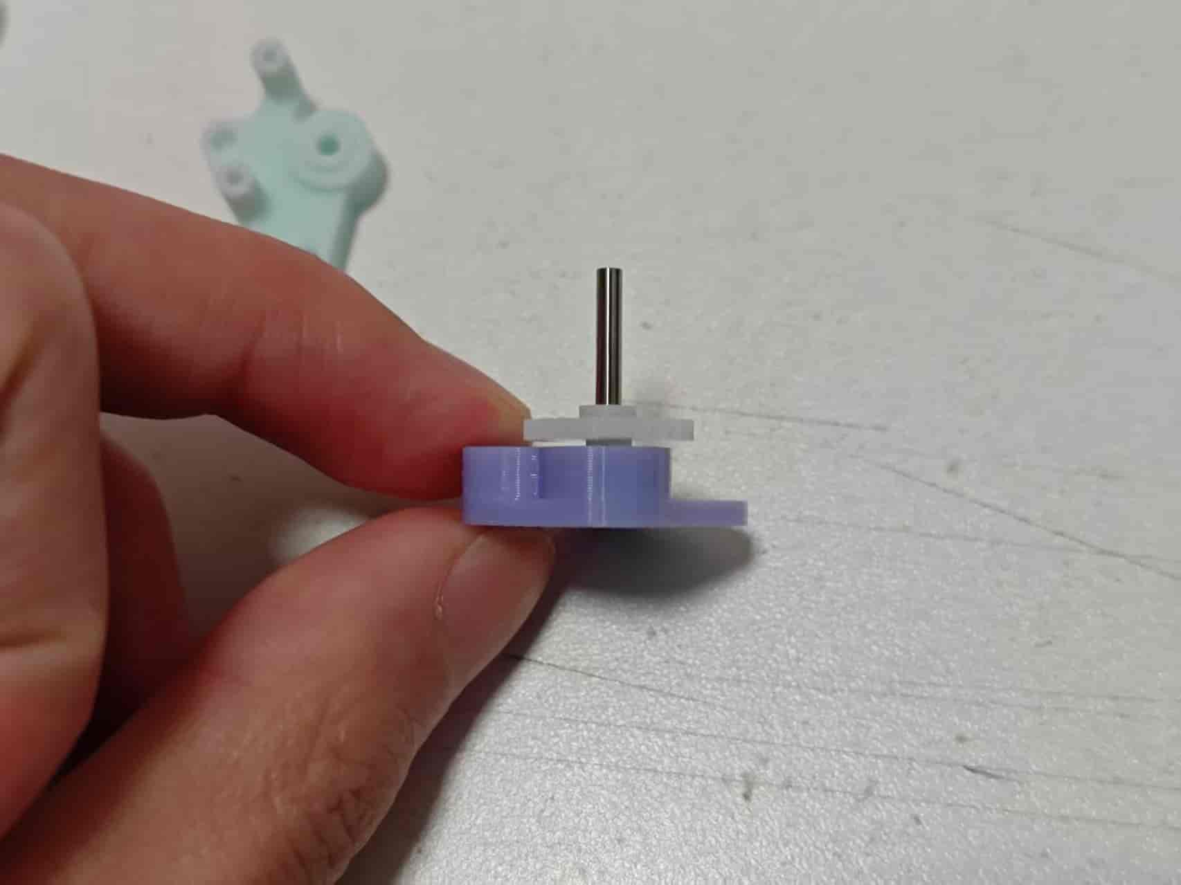
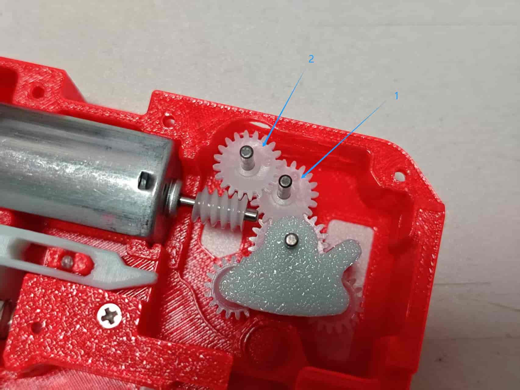
Take one 242A gear and one 2x20mm shaft and assemble. Use the installation aid as shown in Image 1 to press it to the correct depth. The thinner stepped side of the gear should be ~6.1mm from the shaft end:
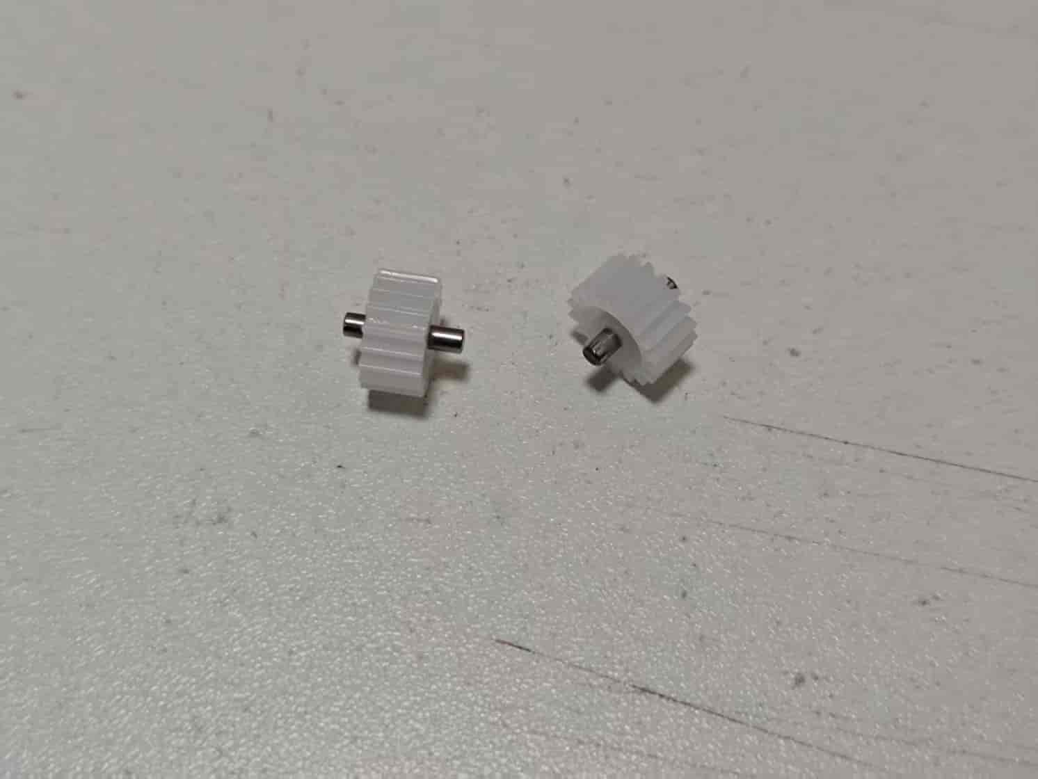
Final assembly of the three gears:
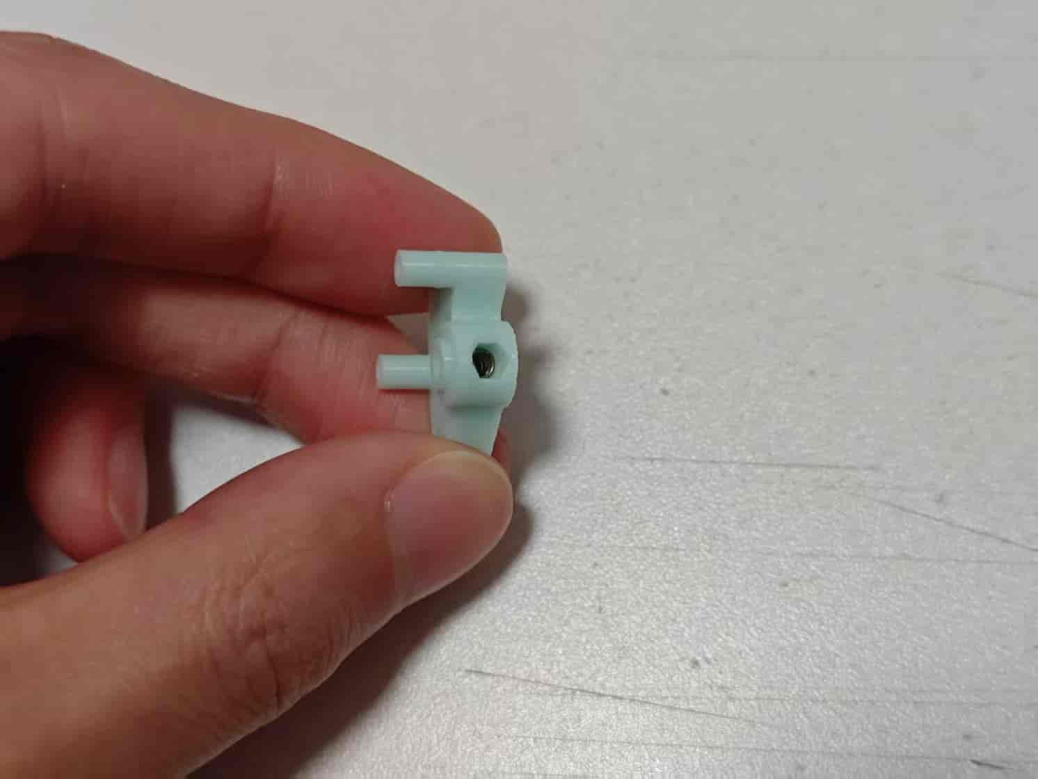
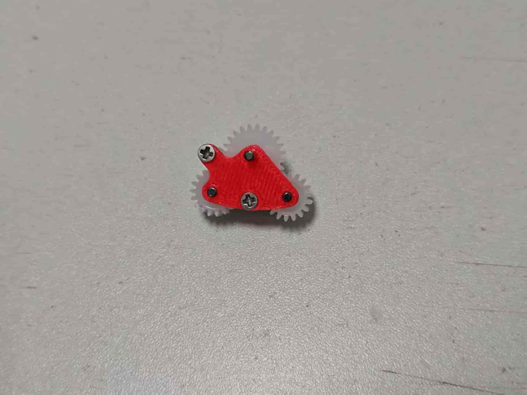
Take Clutch Part B and place a 0.4x3x5mm spring into the side hole:
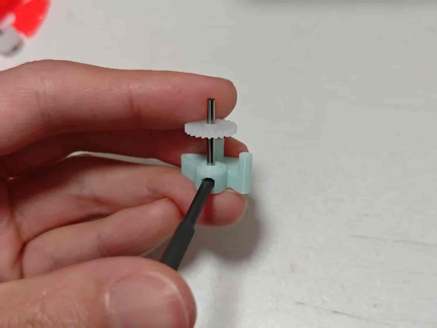
Use a 3mm tool (e.g., 3mm SL screwdriver) to compress the spring. Insert the 242A gear into Clutch Part B as shown (large step downwards, small step upwards):
Insert two 182A gears into the other holes. If a gear is not centered, place the shorter end of the shaft into Clutch Part B:
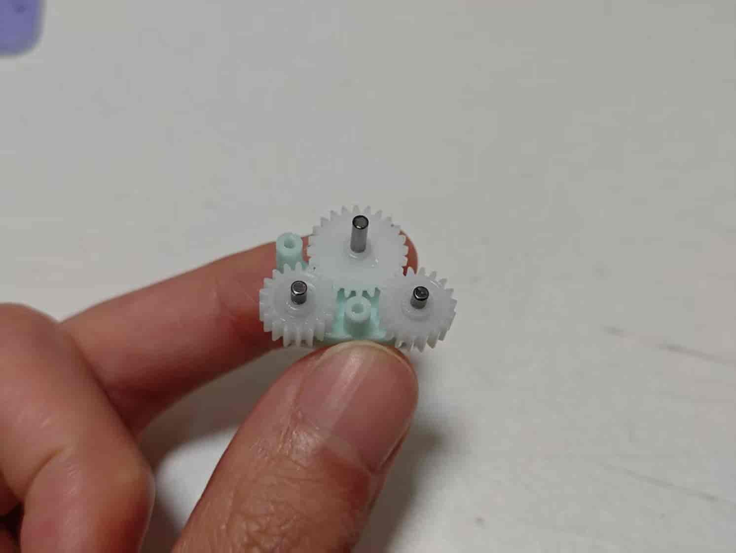
Add Clutch Part A and lock it with two M2x8 screws. The gears should rotate with noticeable spring resistance:
Insert the clutch into the bottom cover as shown:
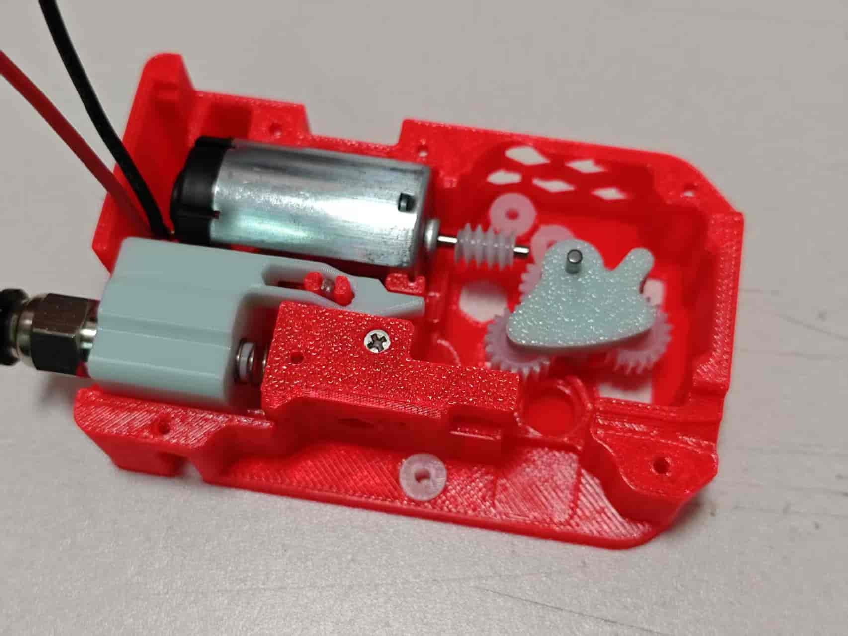
Insert two 20082B gears and a 2x20mm shaft in the order shown:
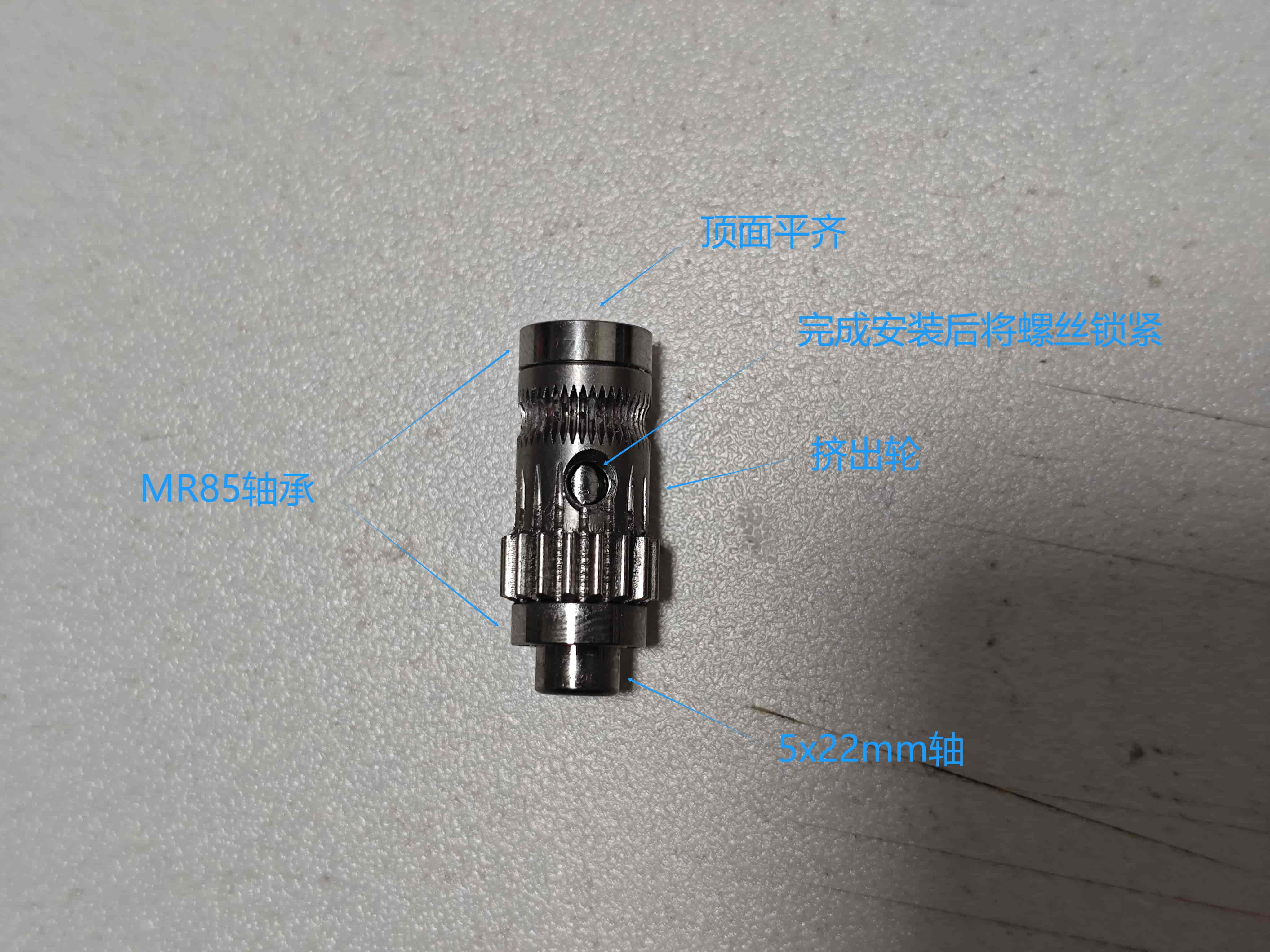
From the BMG parts kit, take the extruder gear with screw holes, two MR85 bearings, and one 5x22mm shaft. Assemble as shown:
Install the assembled extruder gear onto the base. If nothing else remains, now apply grease to all POM gears:
Take the mid-frame and 4 more 62B bushings. Install the bushings into the mid-frame:
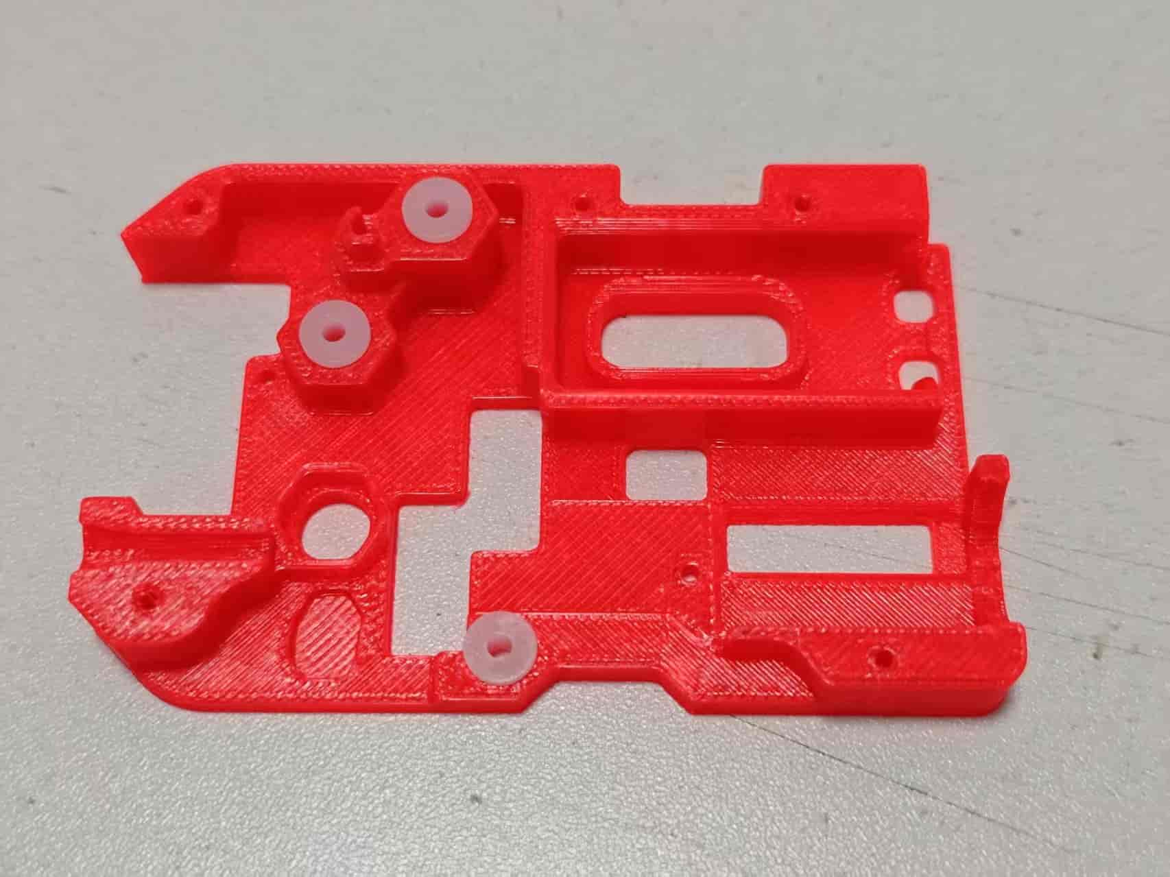
Place the mid-frame onto the bottom cover. Align all shafts into the bushings:
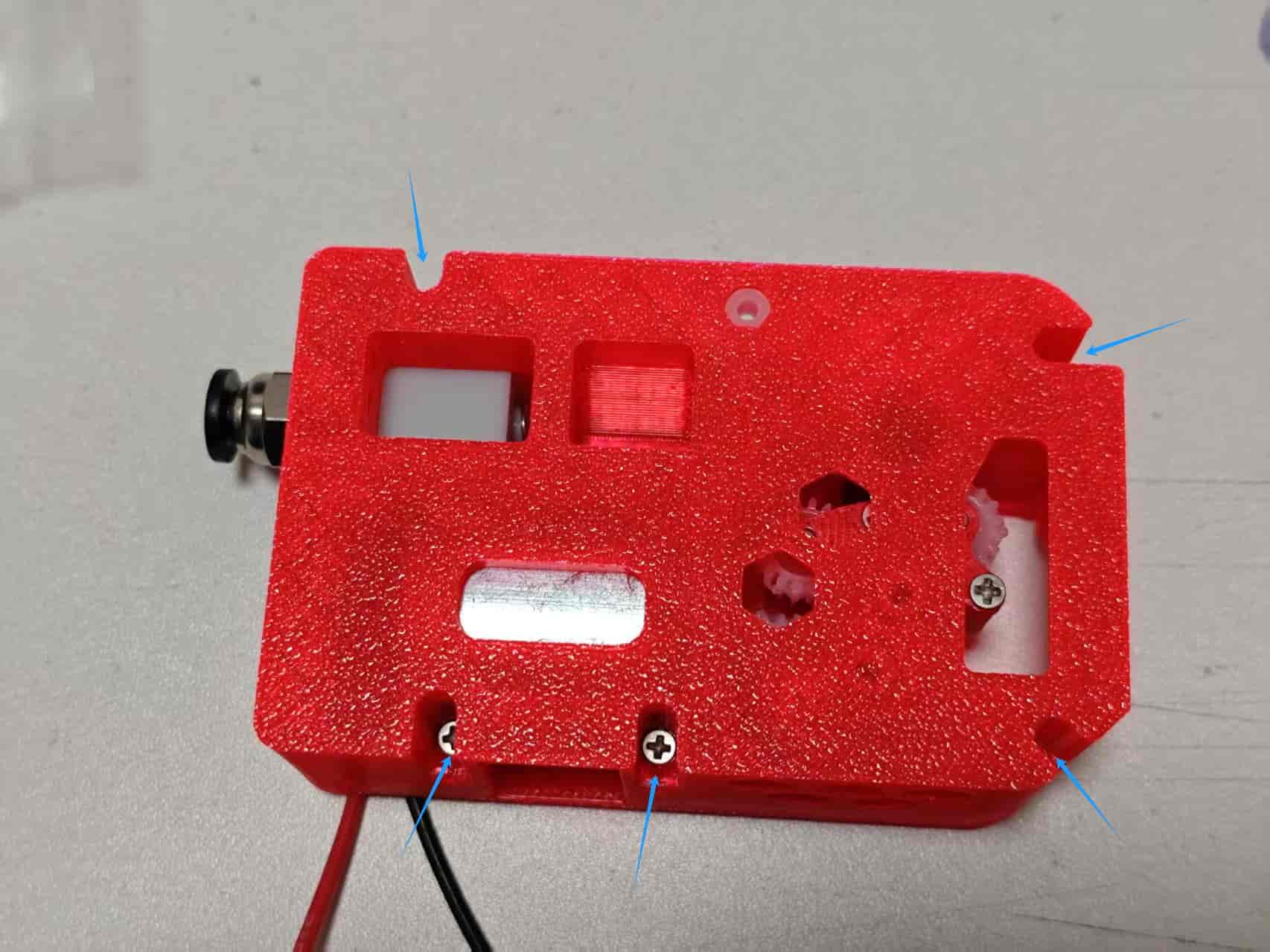
Flip the entire assembly over and fasten all five holes with M2x8 screws:
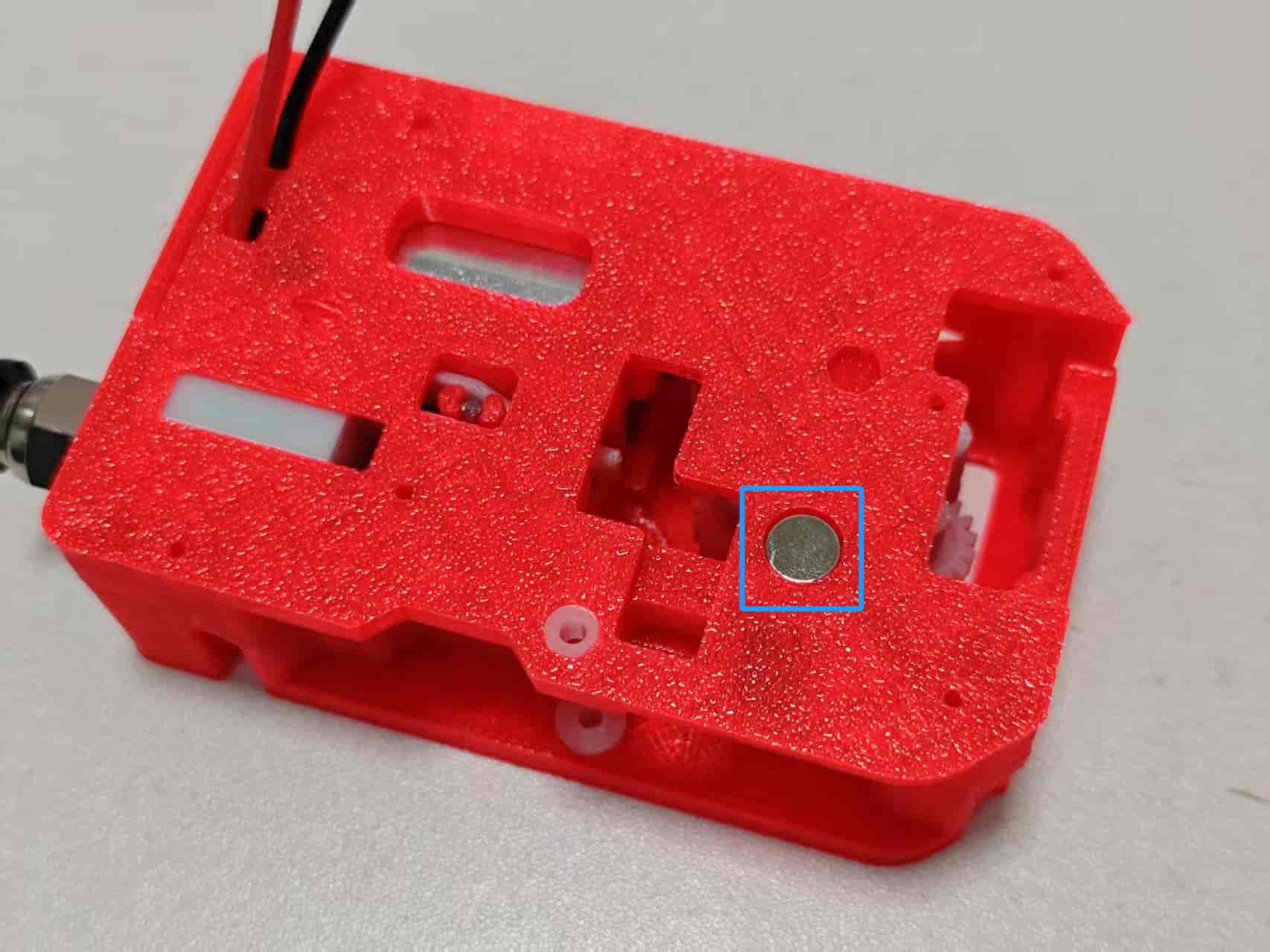
Flip back. Install the magnet, which should rotate with the extruder gear:
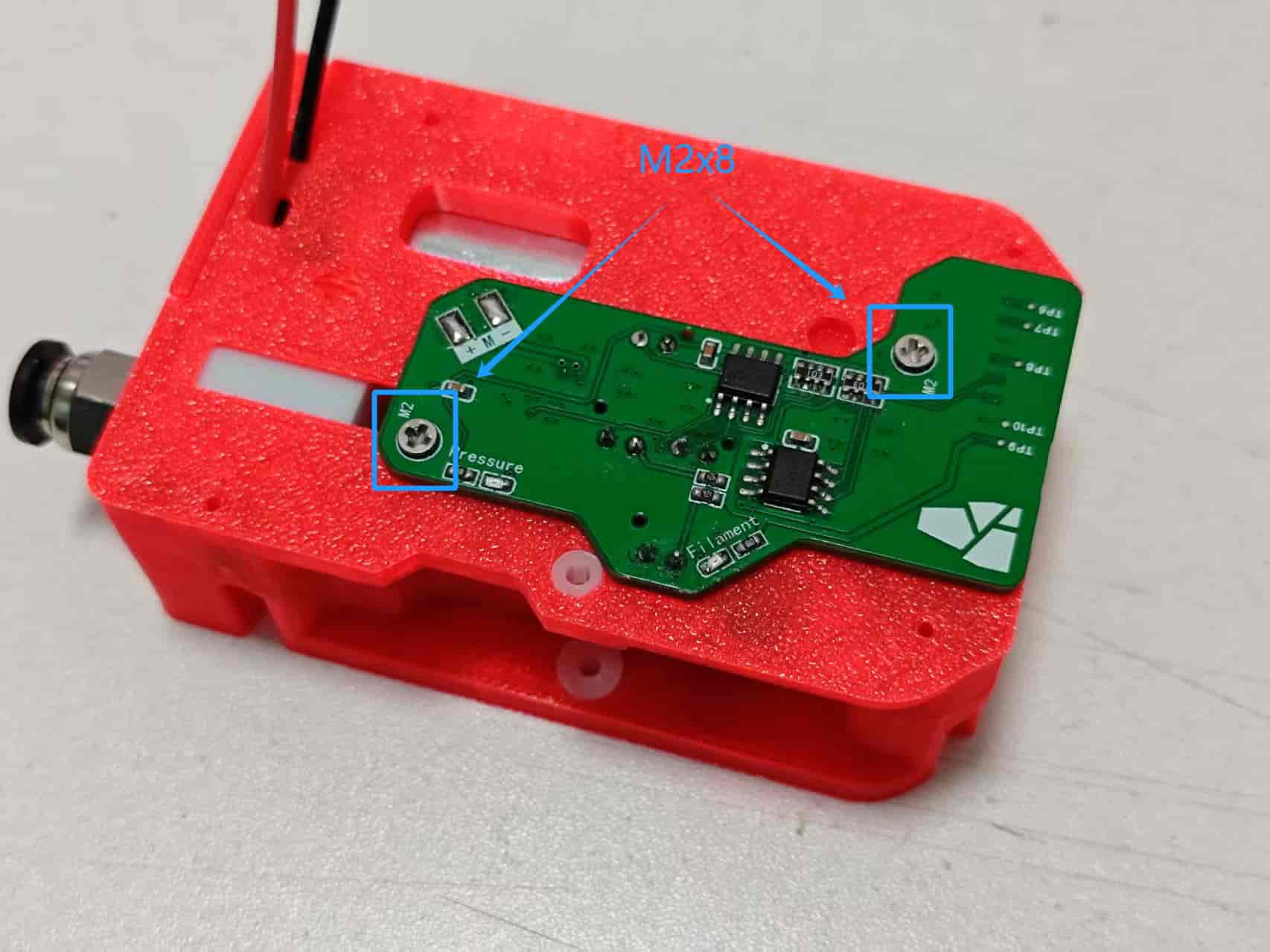
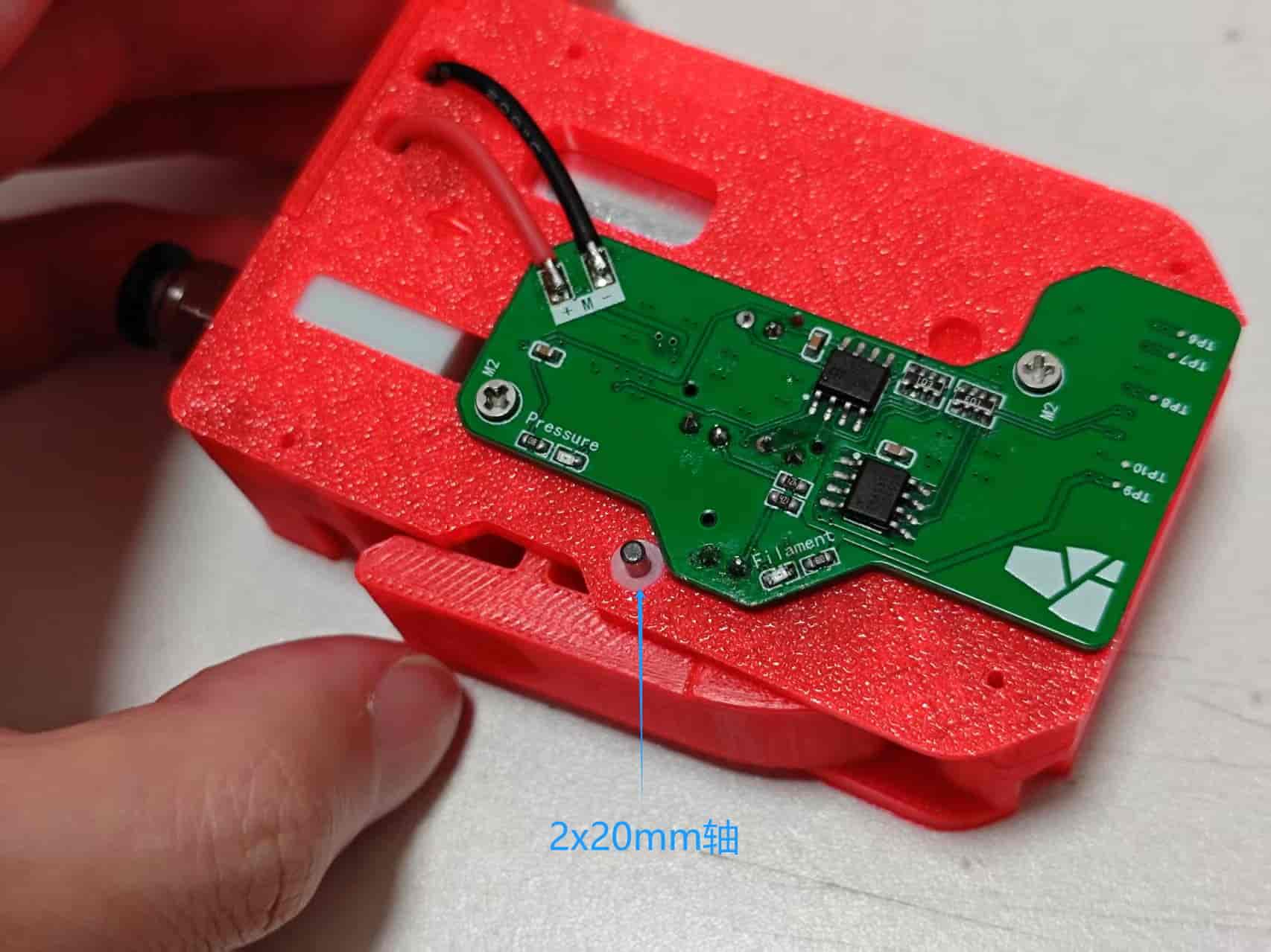
Place the module PCB onto the mid-frame and fasten with M2x8 screws:
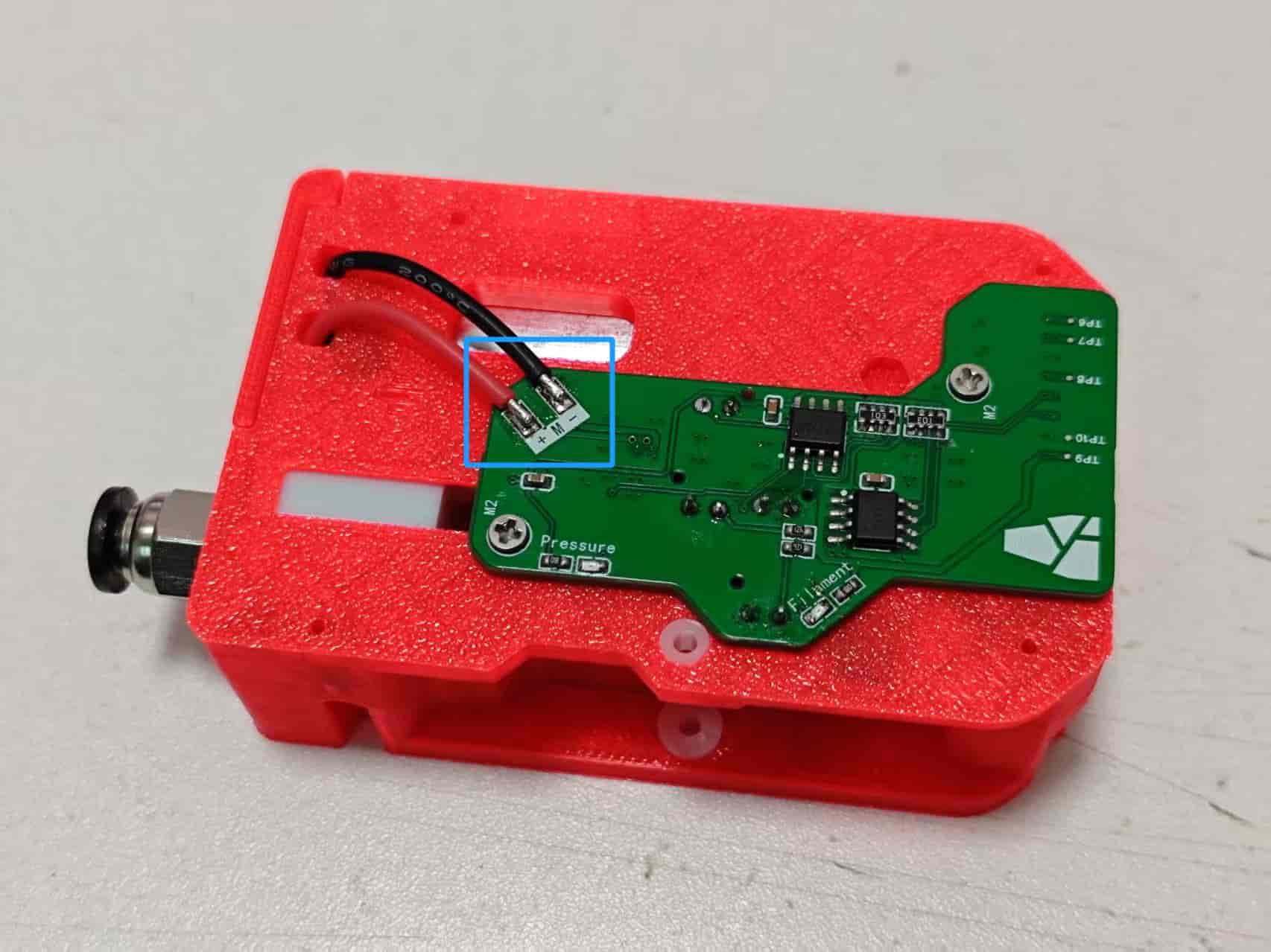
Trim motor wires to proper length and solder to the module board:
Take the handle and insert two needle bearings from the BMG kit into the gear without screw holes. Place the gear into the center of the handle, noting orientation:
Insert the shaft from the BMG kit into the handle. Once installed, the gear should rotate smoothly in the handle:
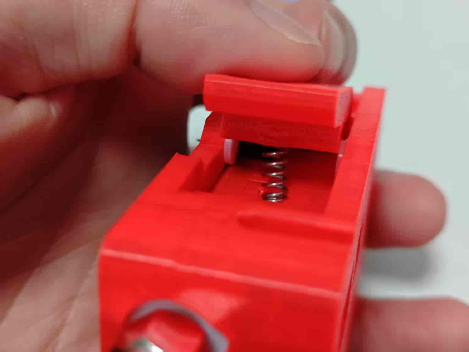
Place the handle onto the module and insert a 0.5x6x10mm spring into the center spring hole:
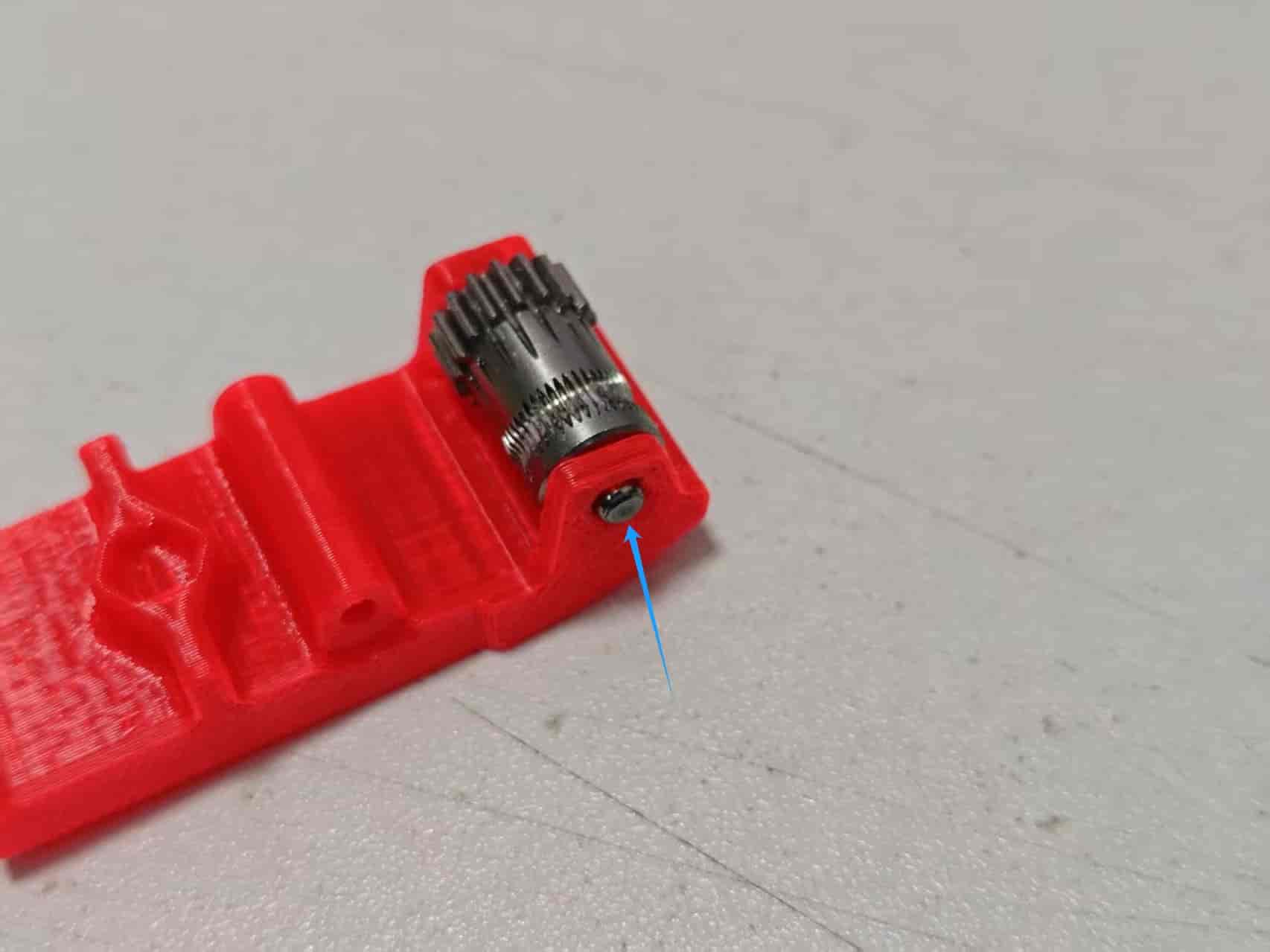
Press the handle down and insert a 2x6mm shaft from the right:
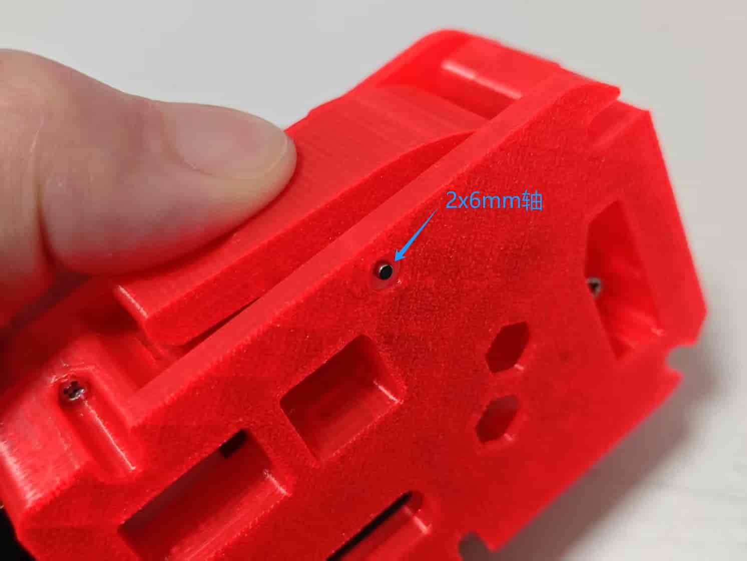
Hold the handle and turn to the other side. Insert a 2x20mm shaft and press all the way in. It should protrude slightly, as shown:
Now attach the back cover and fasten all four M2x8 screws. One module is now fully assembled.

The remaining three modules follow the same assembly procedure. Once done, refer to the version 130 guide to test the components.