

BMCU-B (370 Steel Ball Version) Assembly Guide
This version and its derivatives are outdated and no longer maintained by the Bambu Lab team
Preface
This article is entirely written by wanzi.
This is an assembly guide for the 370 steel ball version compatible with firmware version 3-14, and it is also somewhat applicable to other steel ball versions.
If you don't have the parts yet, please purchase them from the Parts List.
I made this guide when I was passionate about it. If it helps you, feel free to support me at Support Wiki Operation~ 😊
Preparation before Assembly
You need a fully soldered BMCU circuit board, ensuring no soldering defects (such as cold solder joints, missing joints, solder bridges, wrong soldering, etc.), then flash the firmware onto it. The firmware flashing tutorial can be found in the group files for now.
You need to flash firmware version 3-14, which is compatible with both A-series and P-series.
The integrated package for this tutorial: Download 3-14 Package Here, extraction code: wanz
Feeding Component Assembly
Component Name Introduction
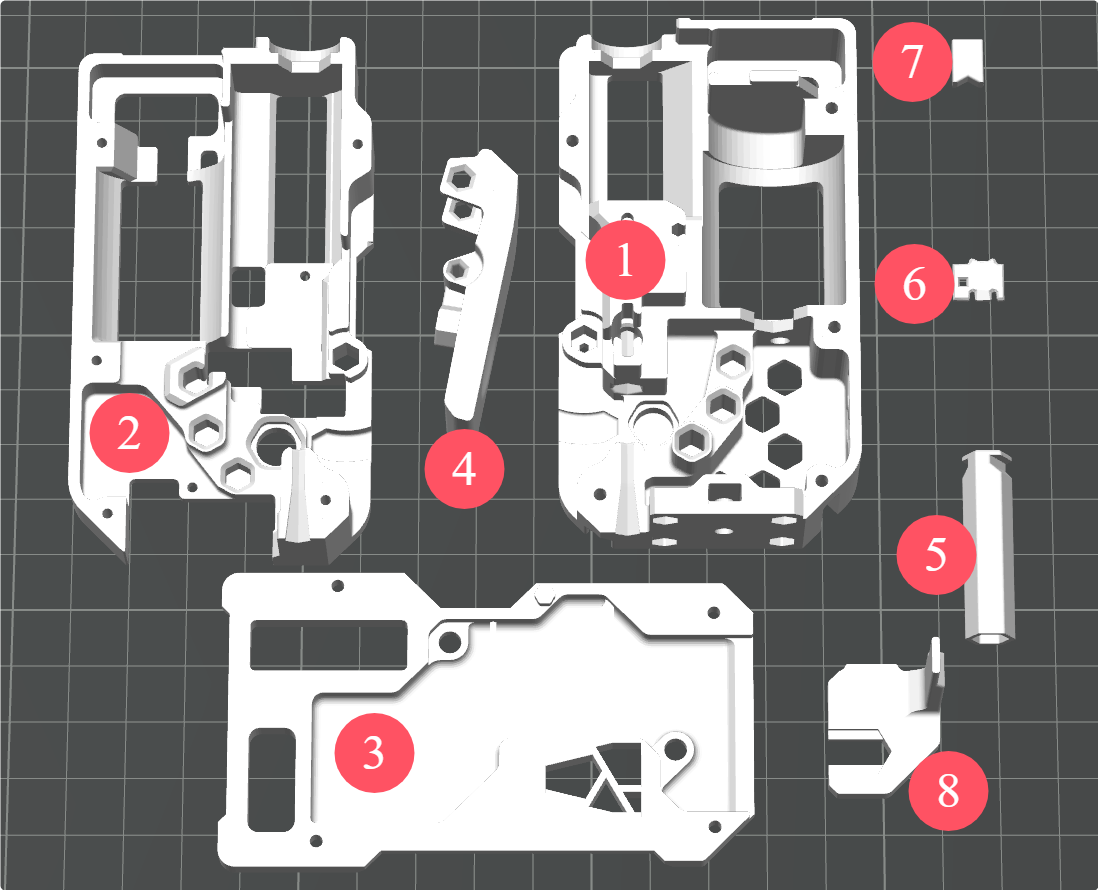
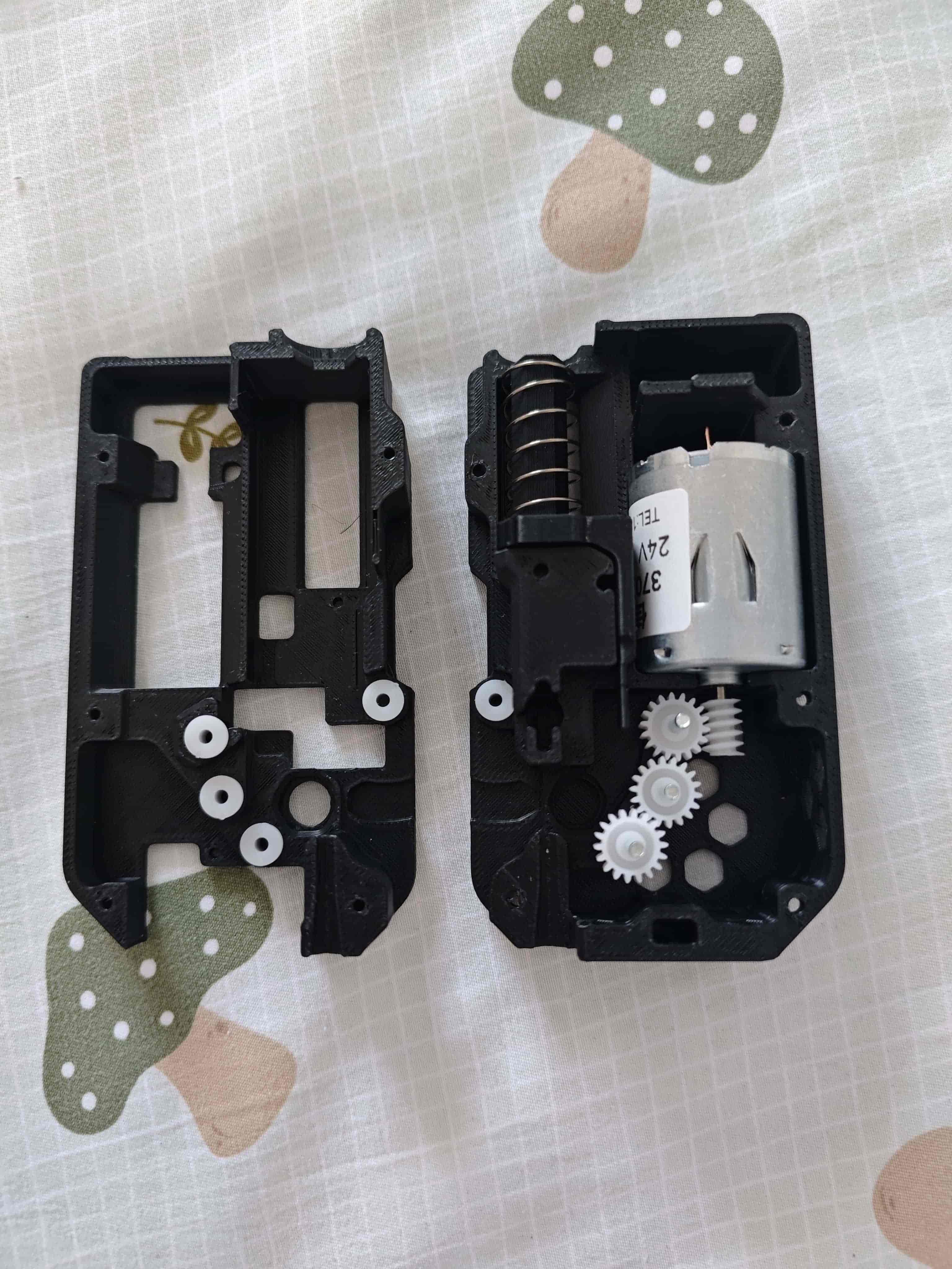
- ① Back Cover
- ② Middle Frame
- ③ Front Cover
- ④ Wrench
- ⑤ Slider Post (Buffer)
- ⑥ Steel Ball Slider / Material Break Slider
- ⑦ Nut Plug
- ⑧ Slider (Buffer)
Installing the Shaft Sleeve
Insert the 62B shaft sleeve into the back cover and middle frame as shown below.
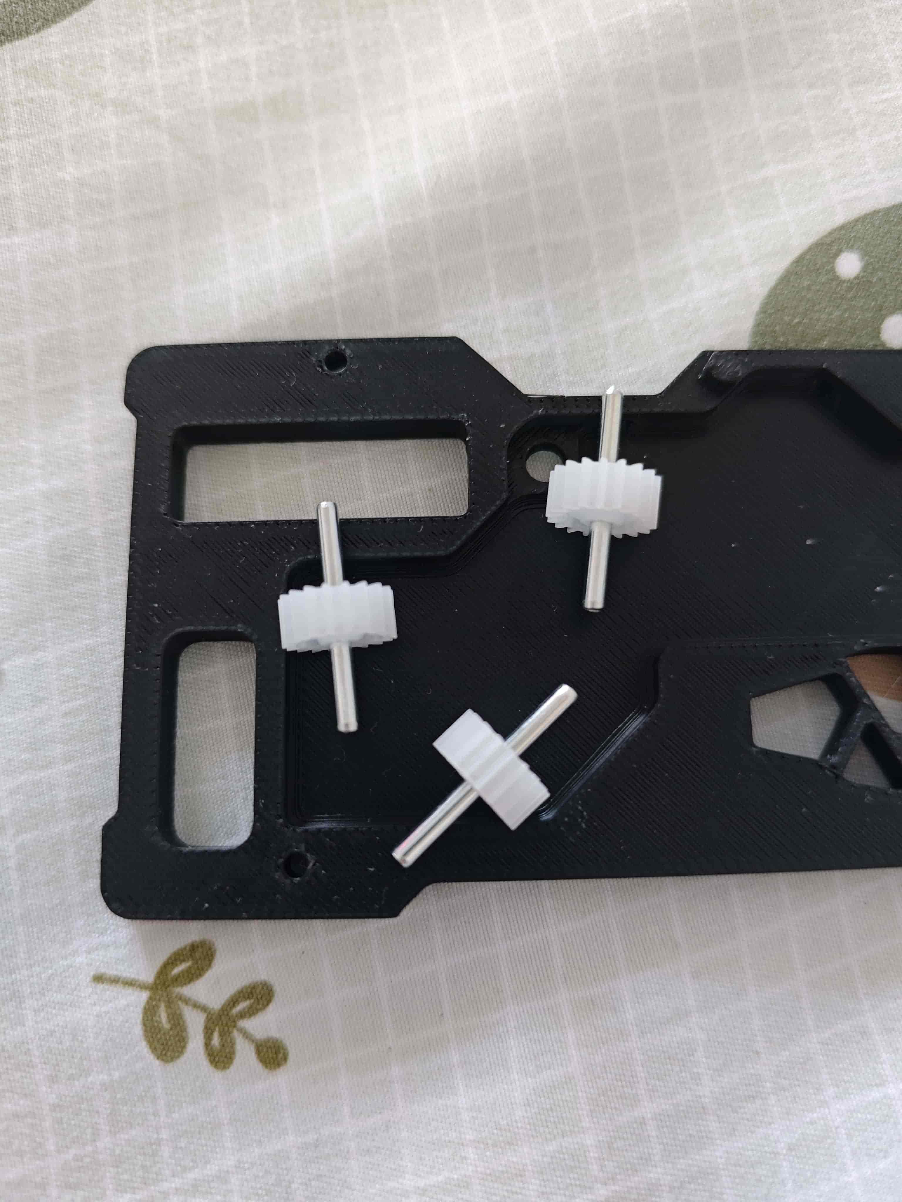
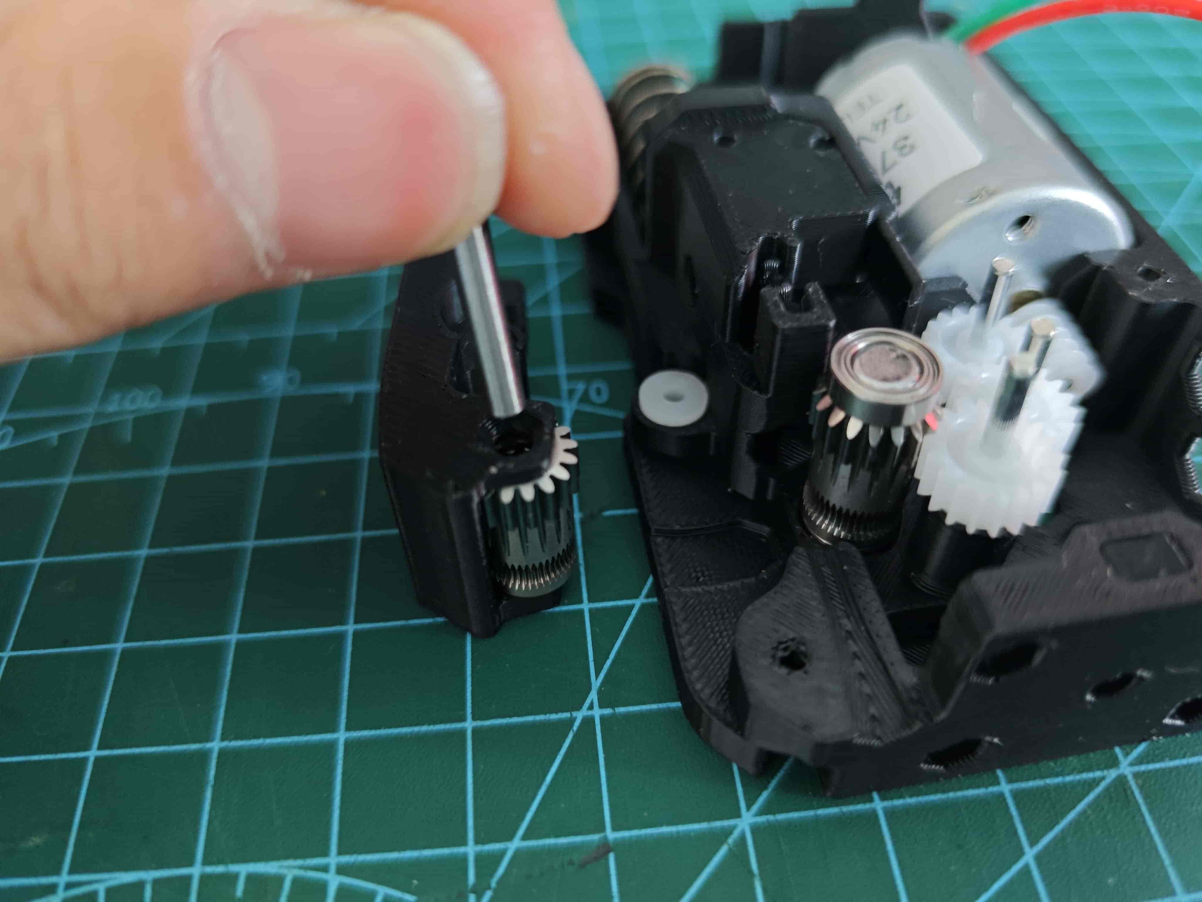
Assemble the 182A Gear and 2*20 Shaft
Press the shaft into the gear as shown, making sure both ends protrude roughly equally.
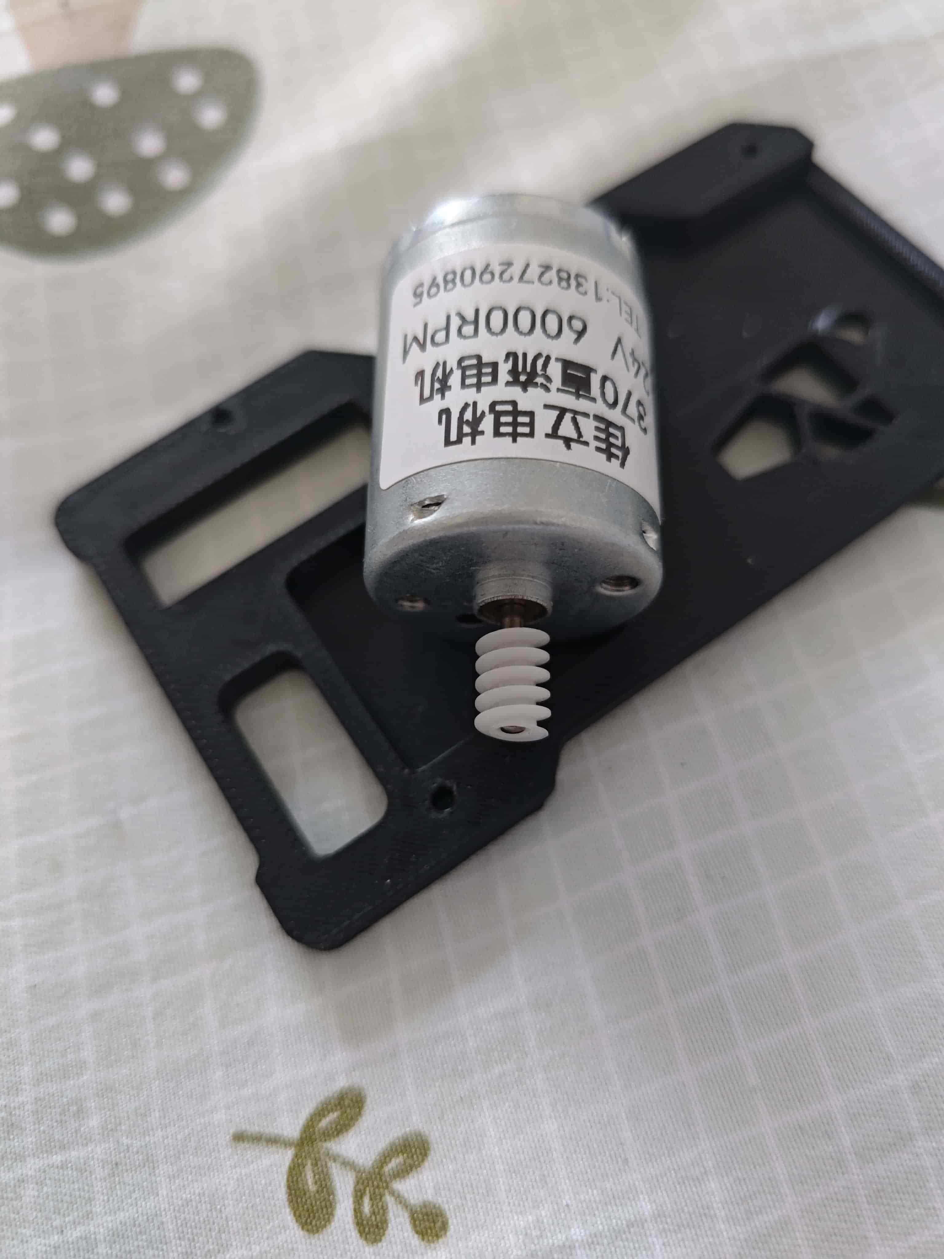
Install the Worm Gear on the 370 Motor
For motors purchased from "Jiali Motor," press the worm gear all the way down; the length fits perfectly.
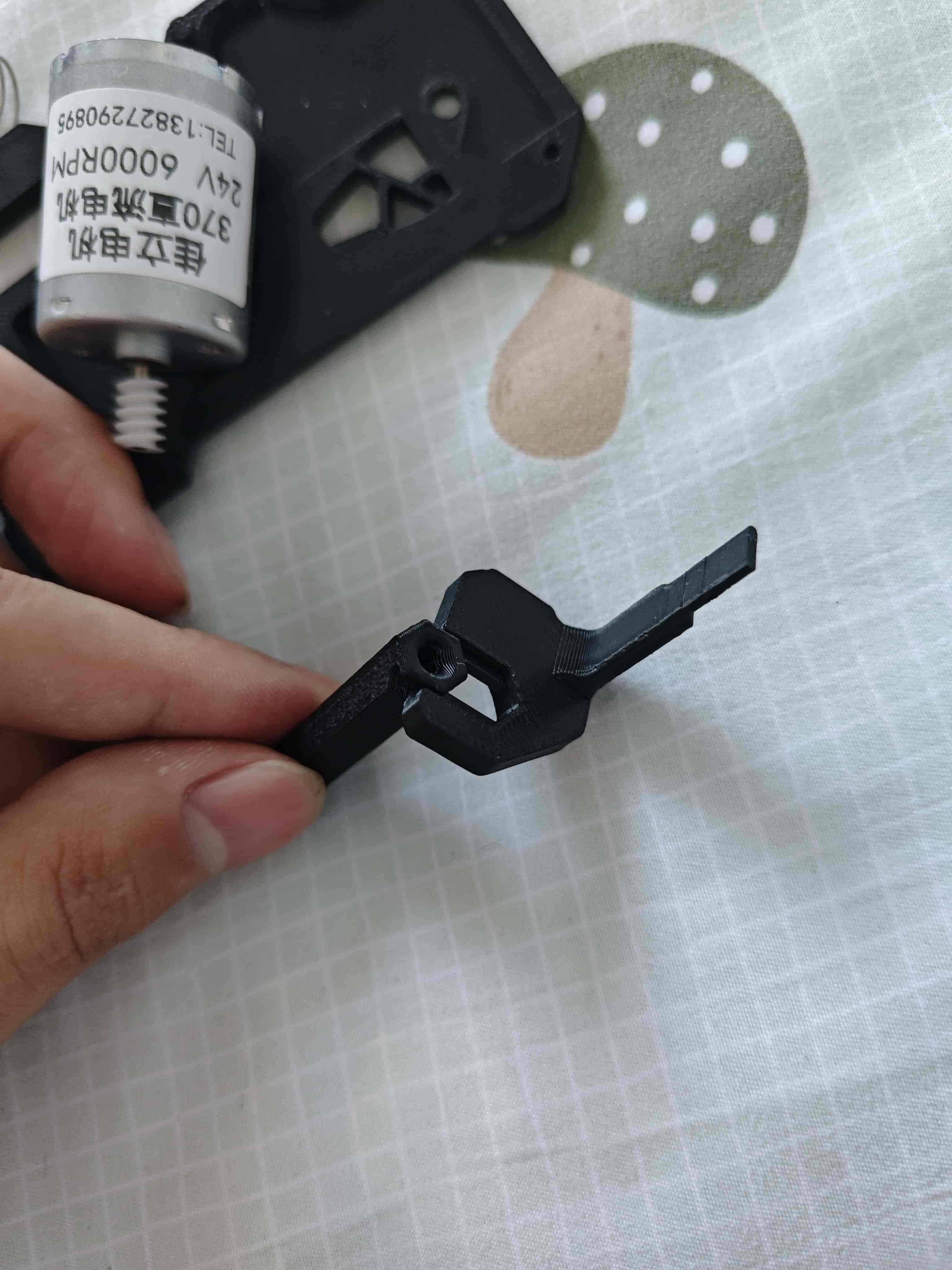
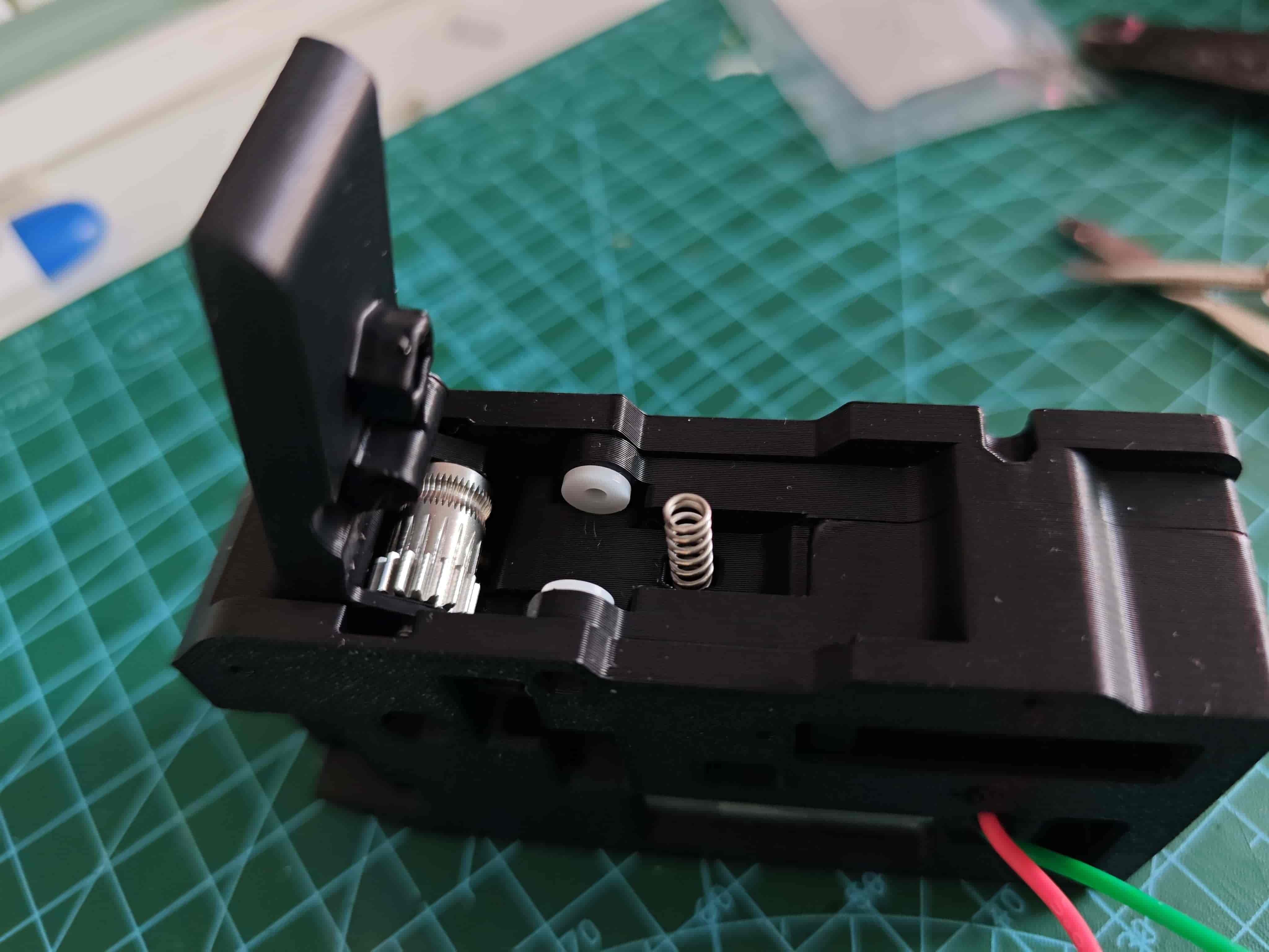
Assemble the Buffer
Assemble the slider post and slider together.
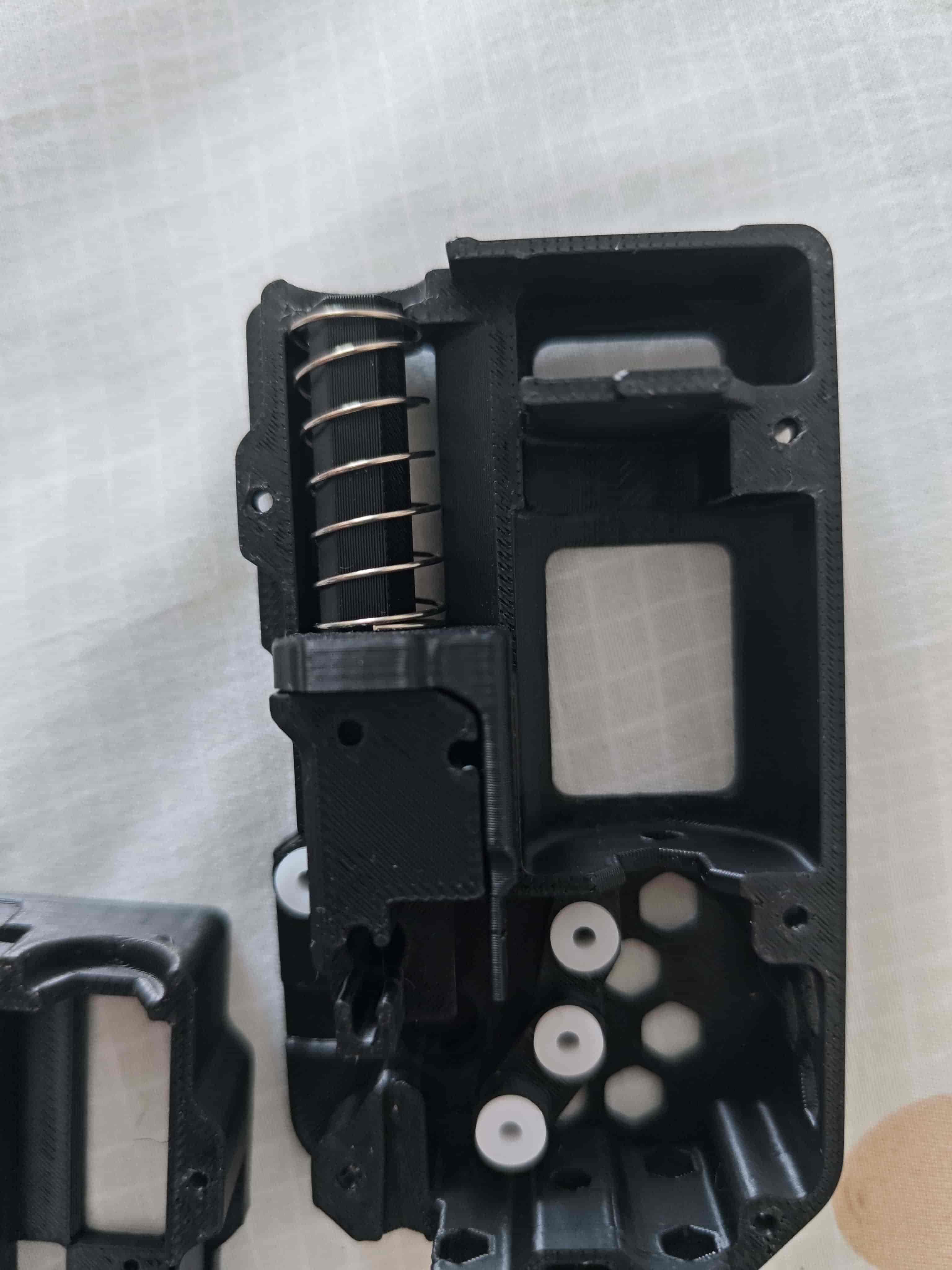
Put a 0.6*12x30mm spring on the assembled buffer and place it into the back cover.
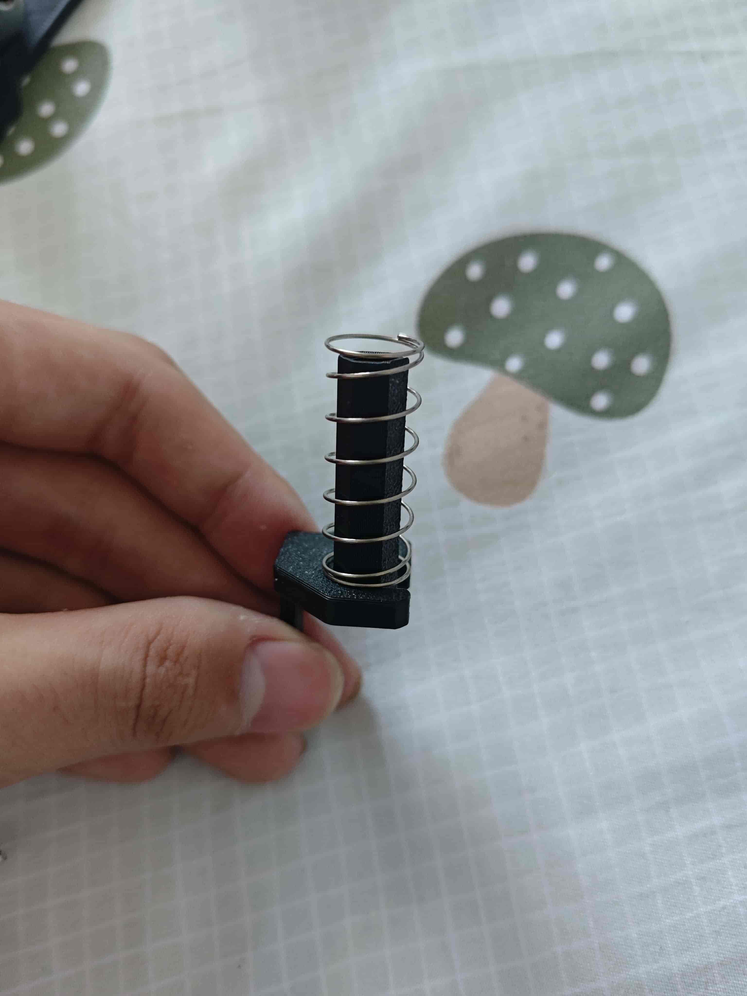
Let the spring clip onto the edge of the back cover.
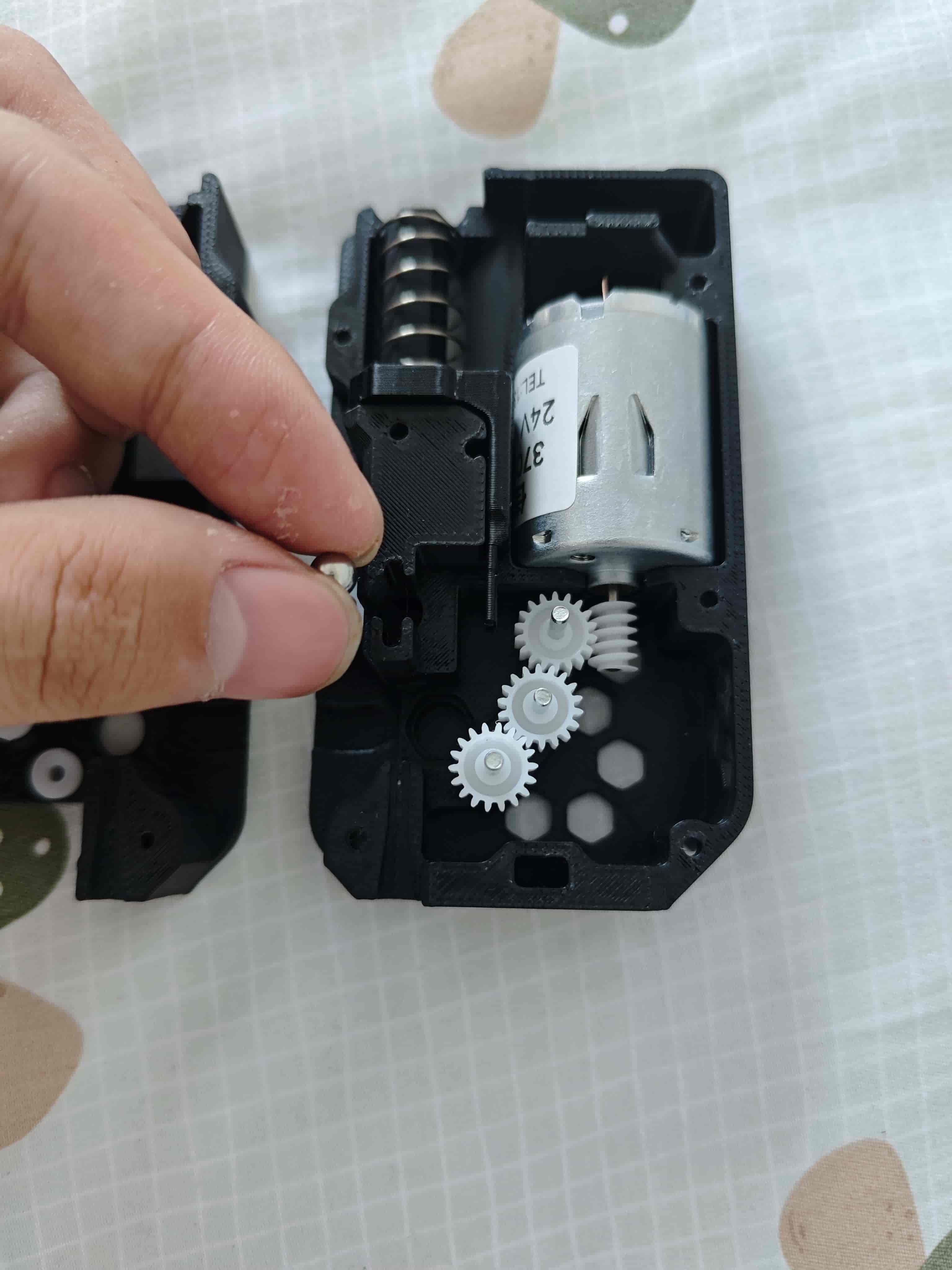
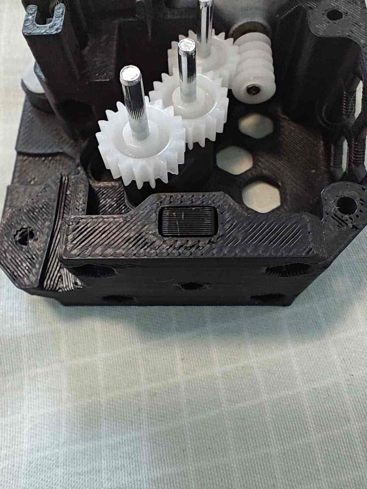
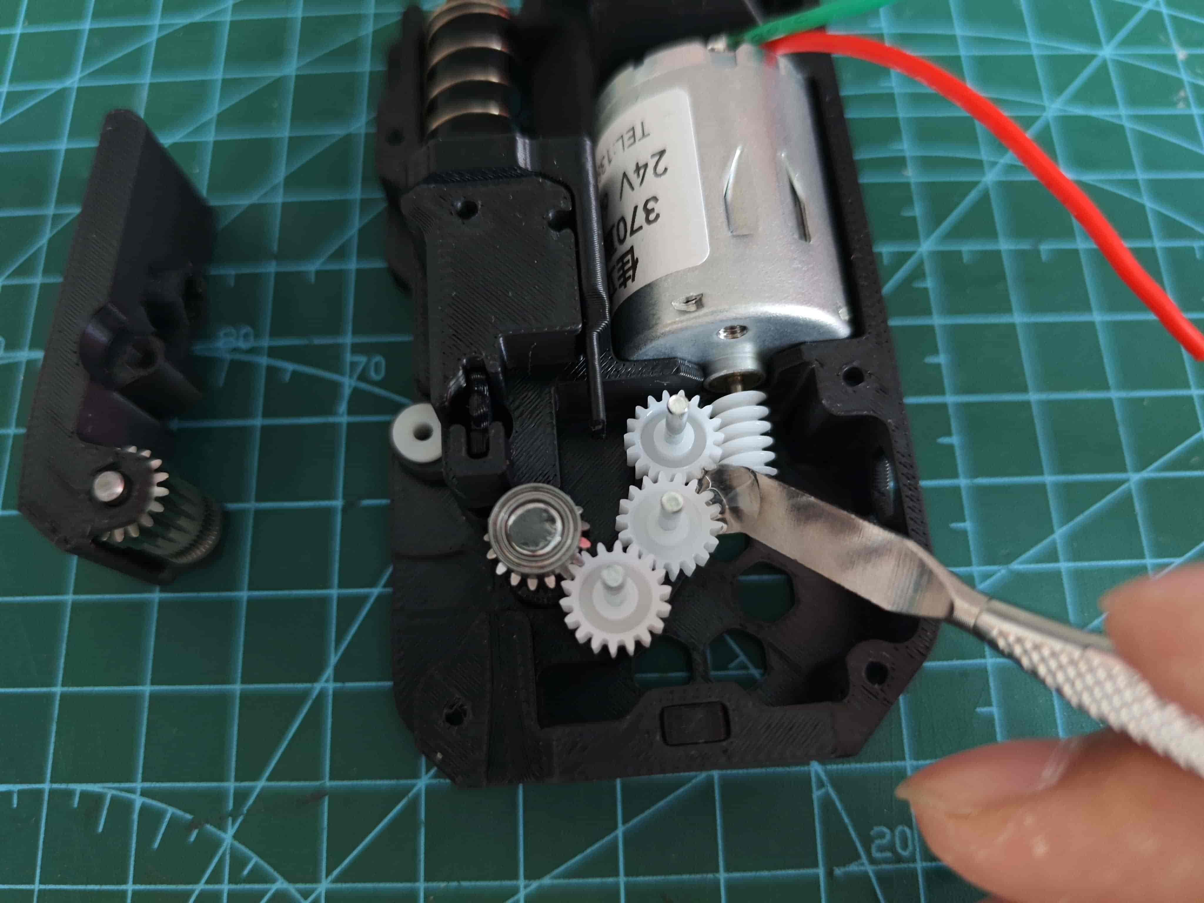
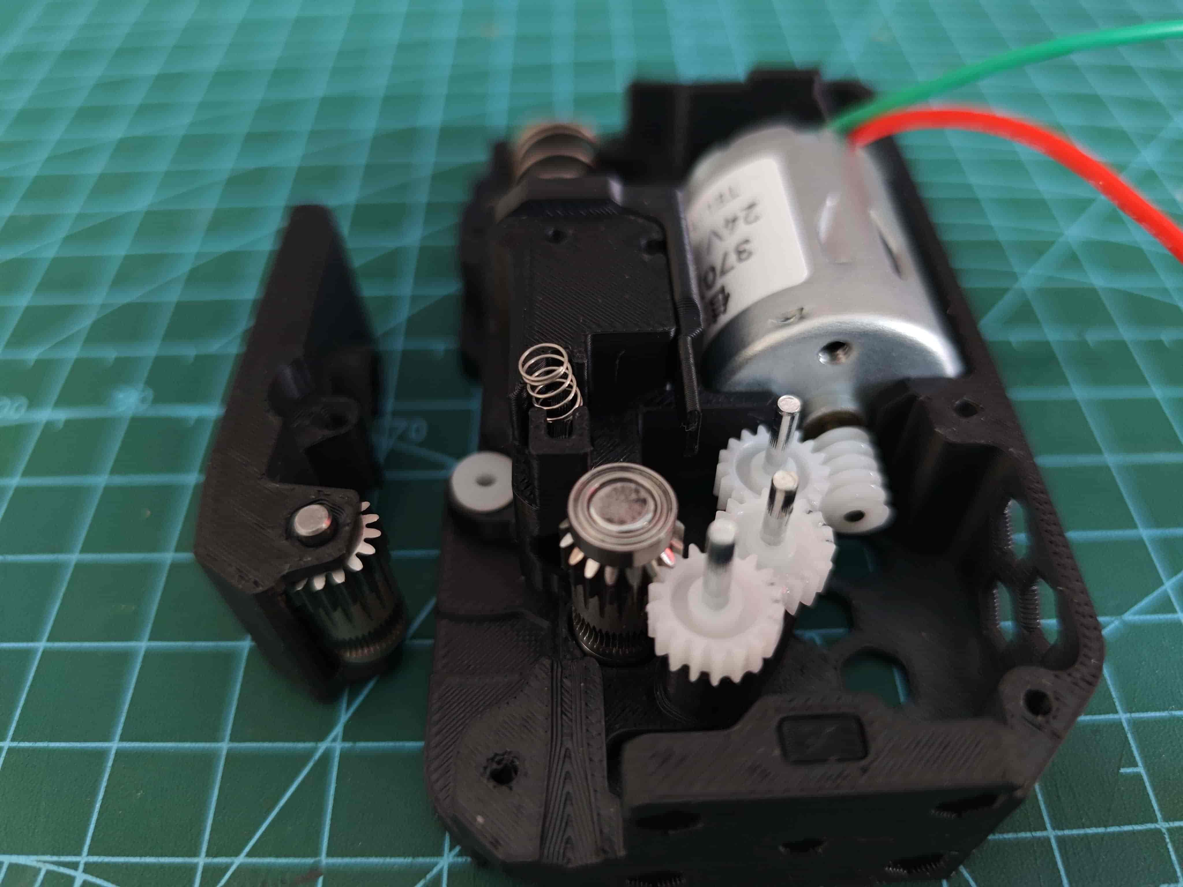
Install Motor and Gear
Place the previously assembled gear and motor into the back cover.
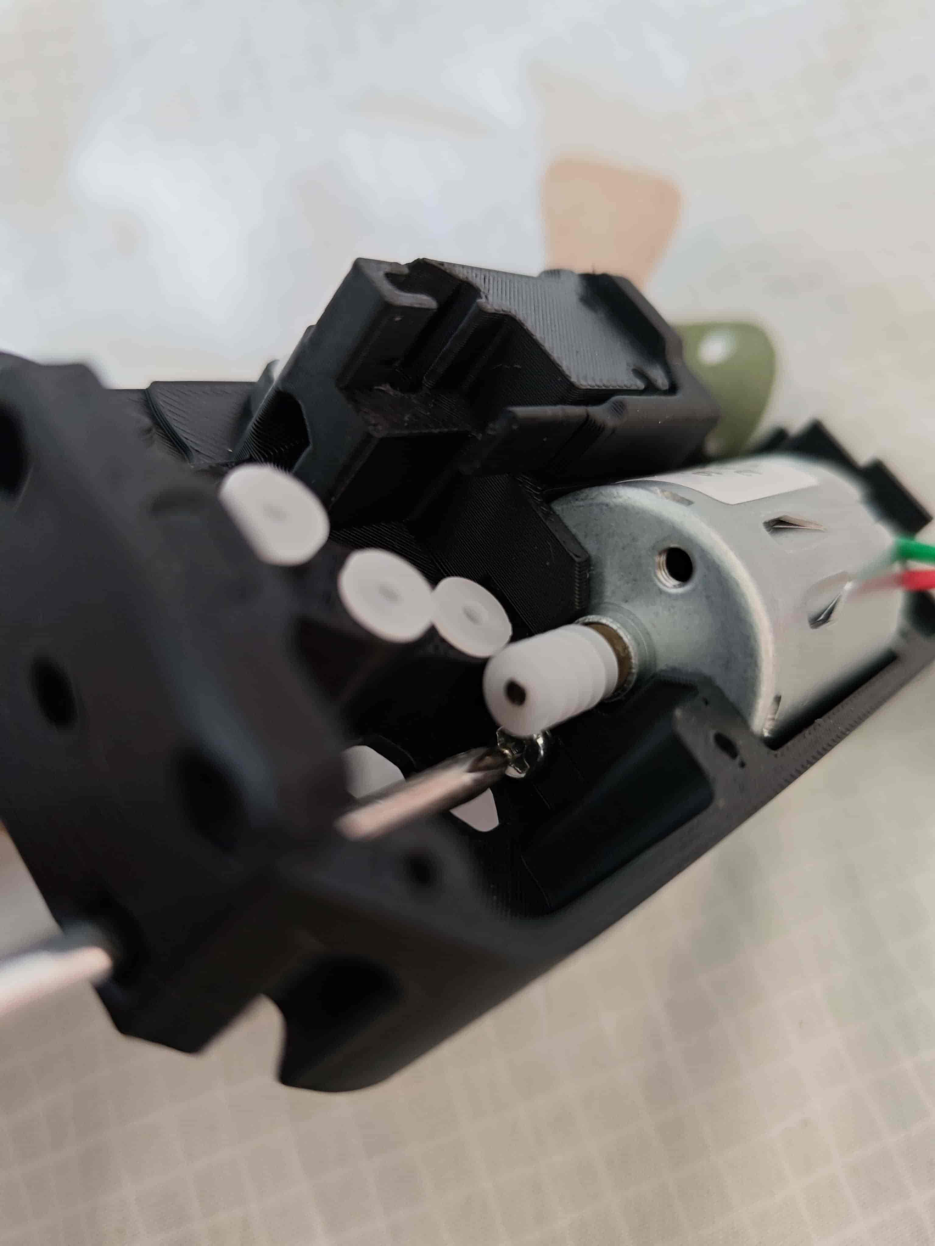
Use a screwdriver through the hole at the bottom to fix the 370 motor with an m3*5 flat-head screw.
Install Material Break Detection Part
Put the steel ball into the back cover as shown.
Then insert the steel ball slider into the back cover.
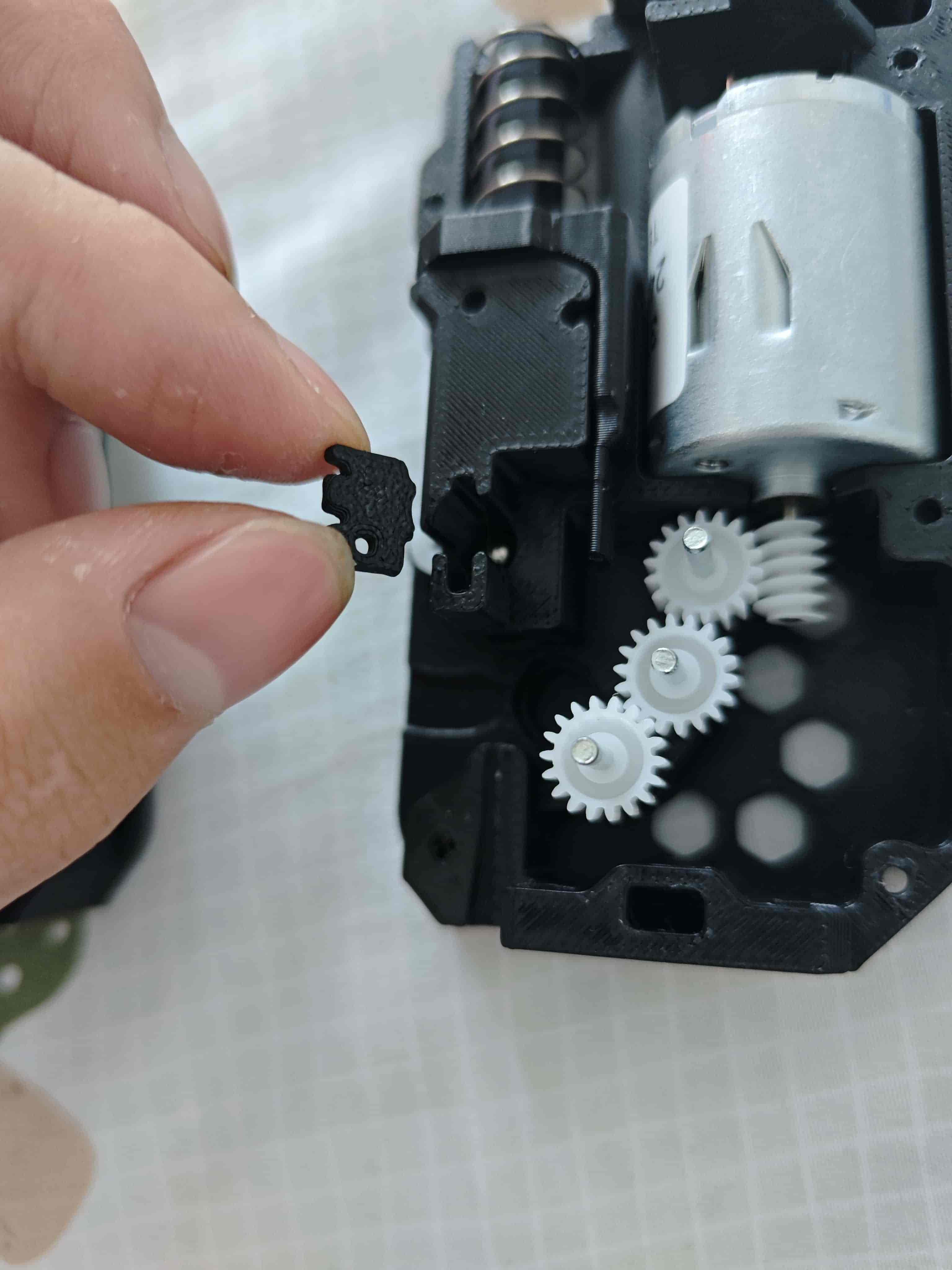
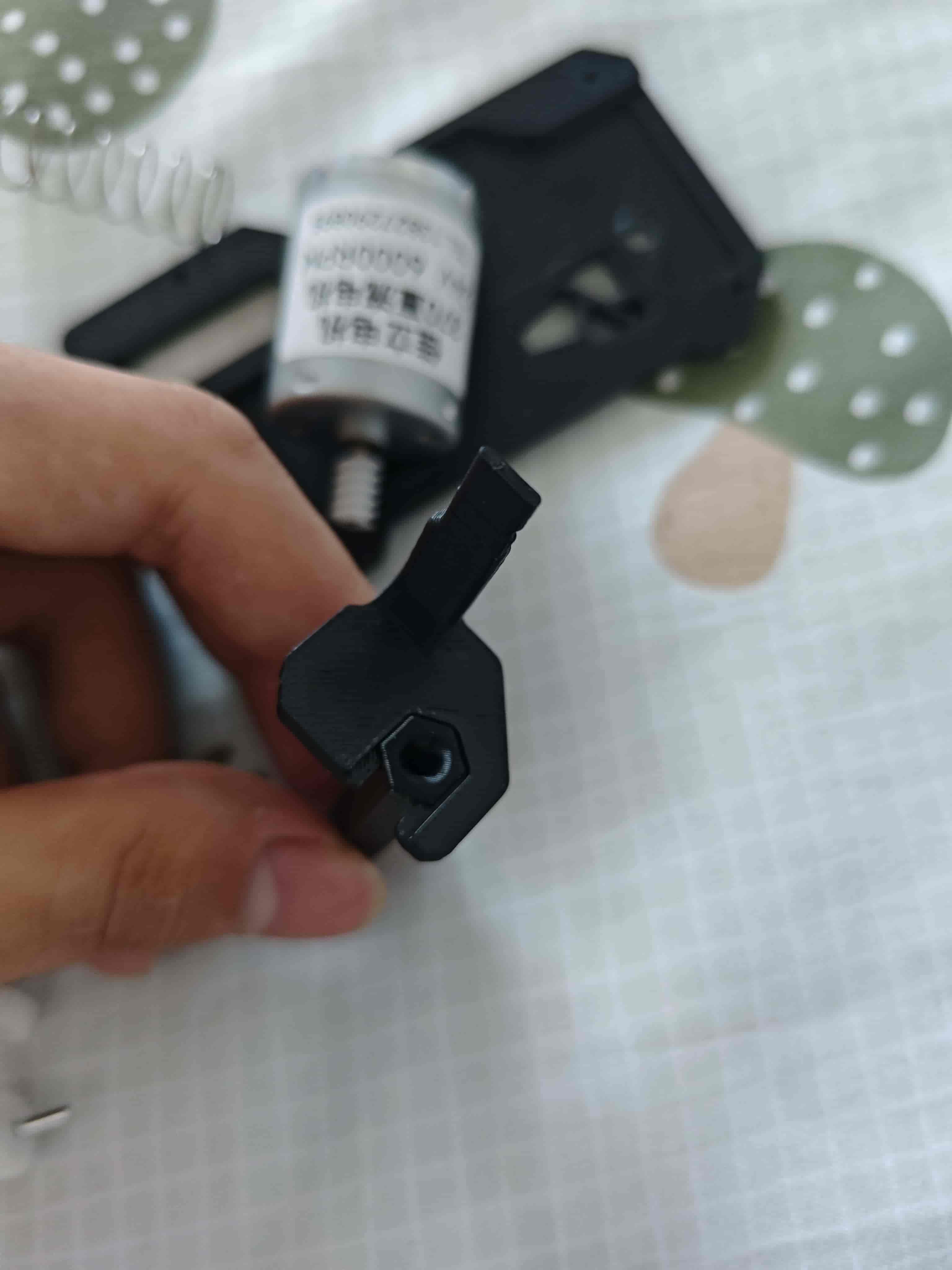
Install Hex Nut
In version 3-14, the self-tapping screw hole here was changed to a nut for machine screws to avoid thread stripping caused by frequent assembly/disassembly of the feeding component and base.
Place the hex nut into the back cover.
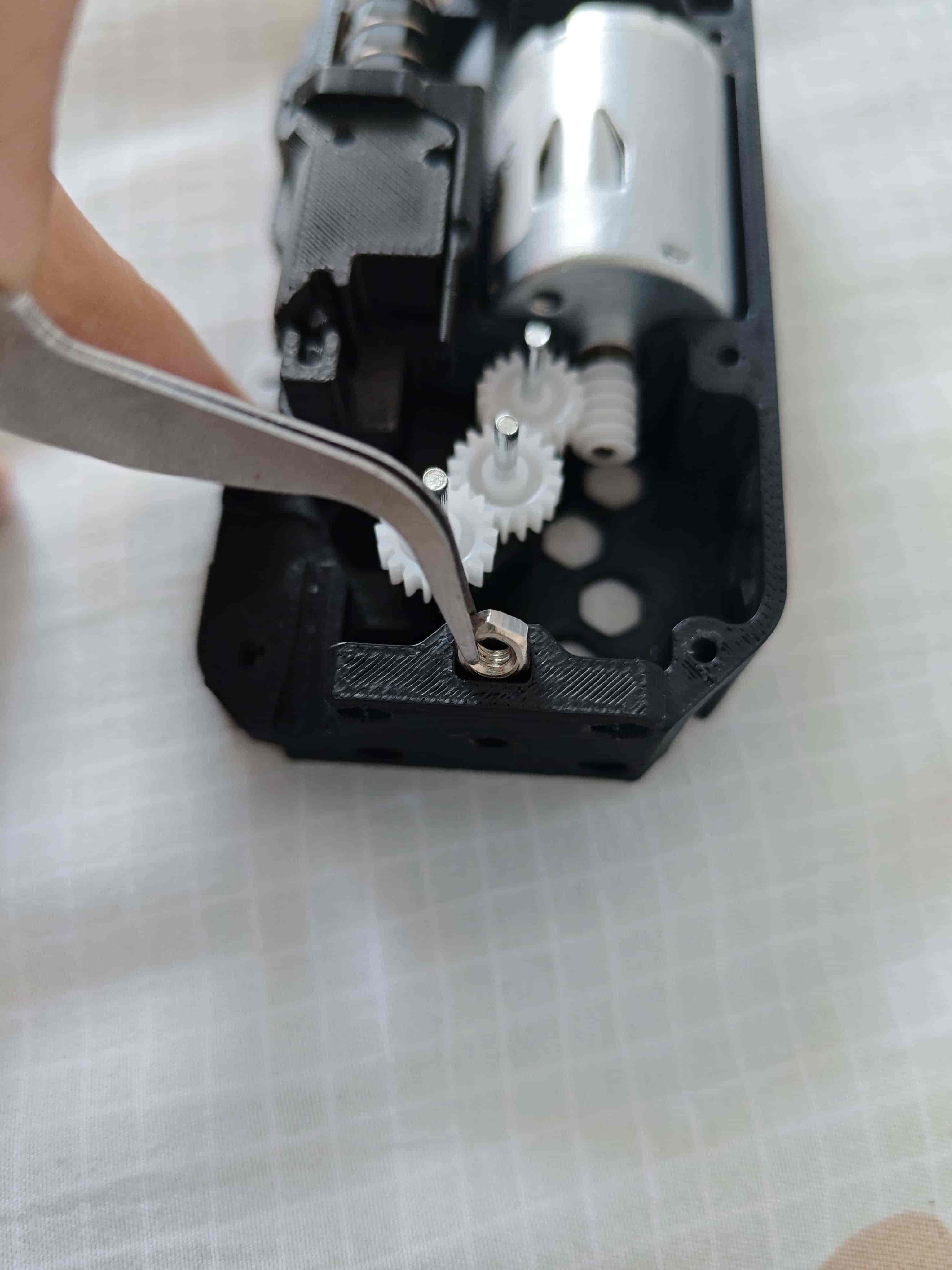
Insert the nut plug to fix the hex nut.
Install BMG Drive Wheel
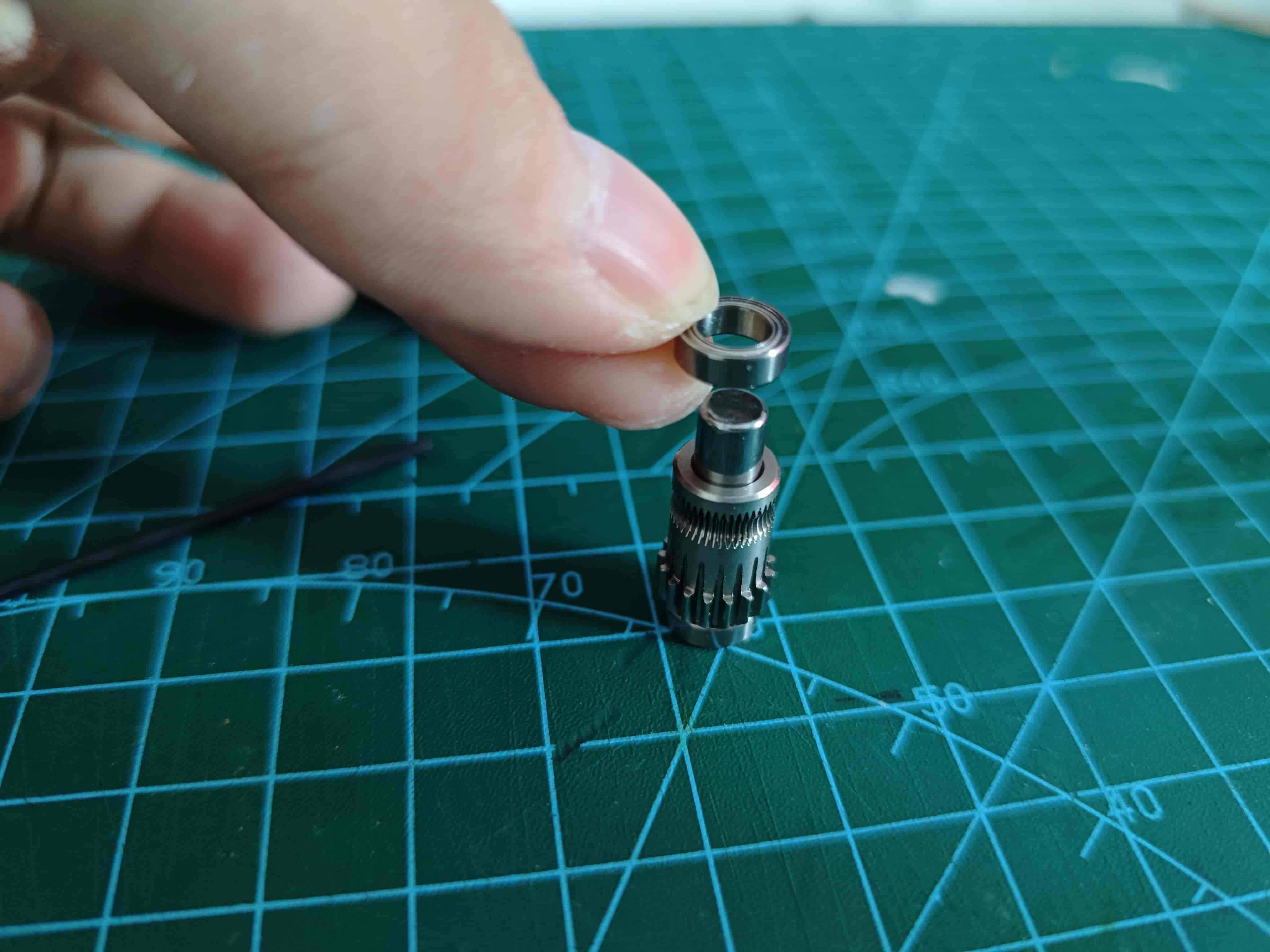
The image below shows all parts of the BMG gear set.
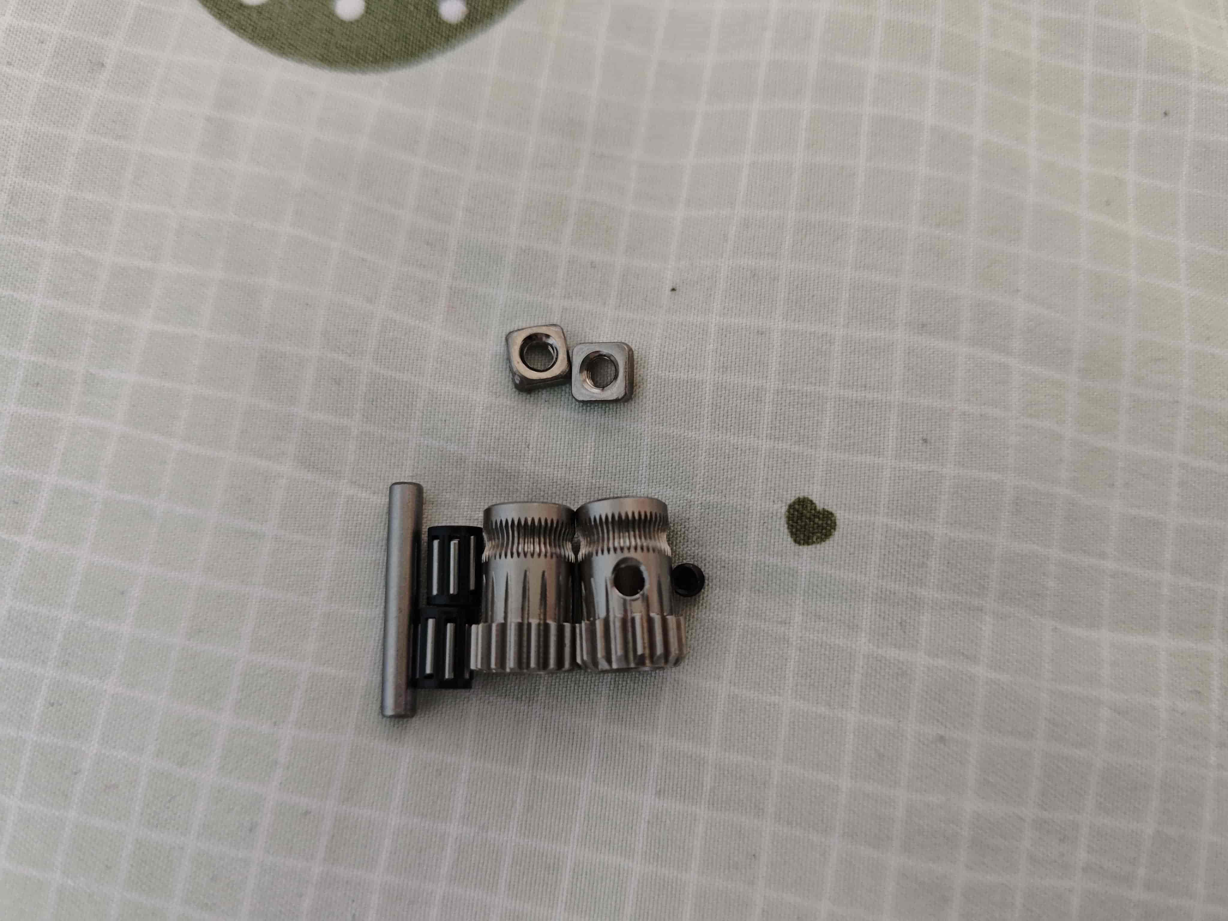
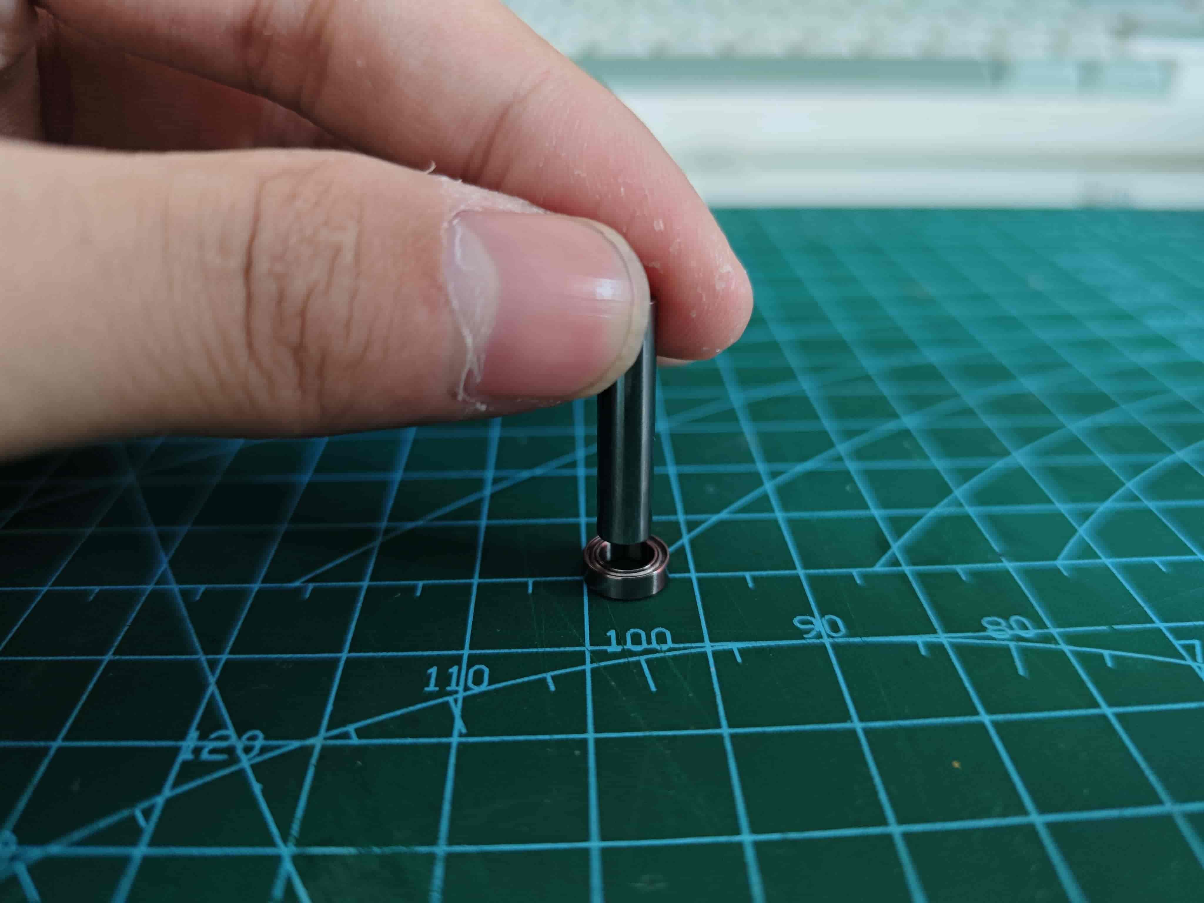
Take one D5x22mm shaft and two MR85ZZ bearings, press the shaft into one bearing so the bottom surface is flush.
Note
Apply even force during installation, keep it level and vertical to avoid bearing jamming or incorrect installation. Also, the shaft is said to have poor precision; please evaluate before use.
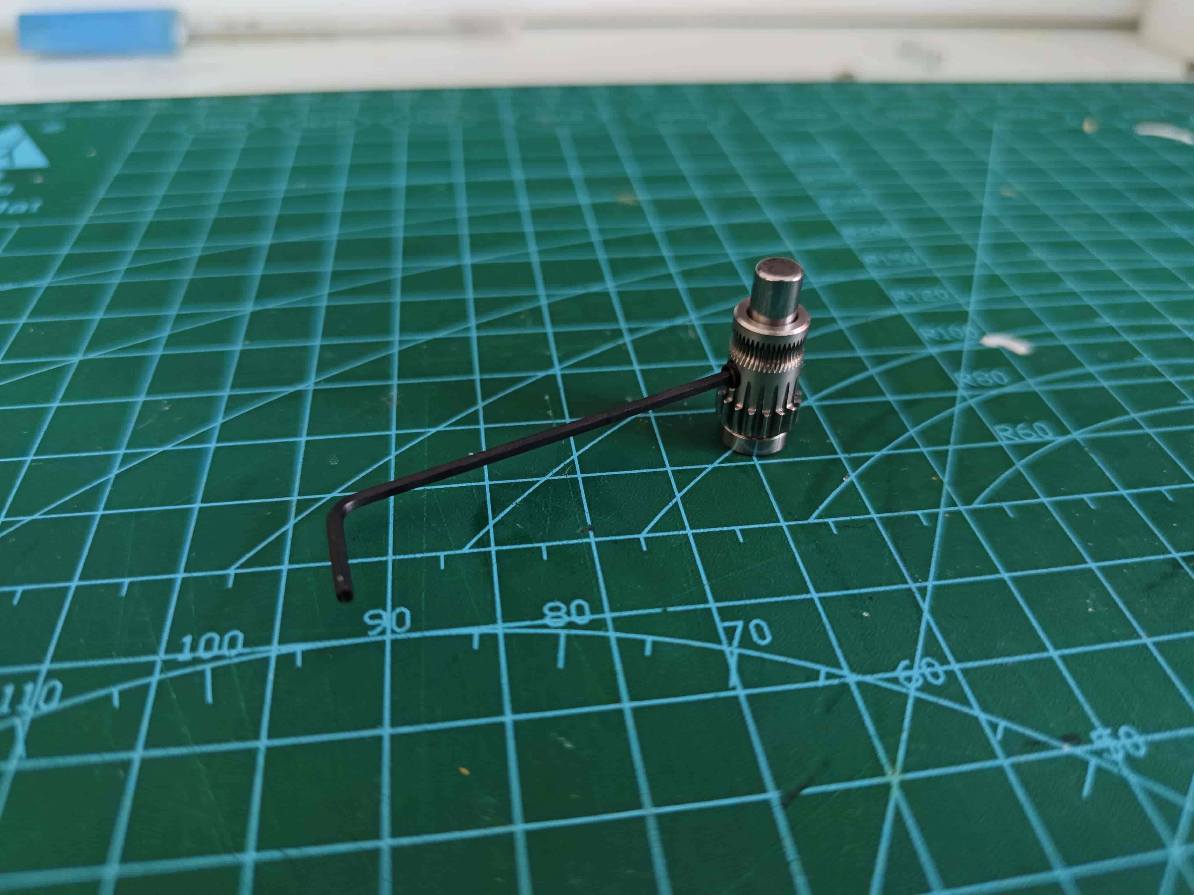
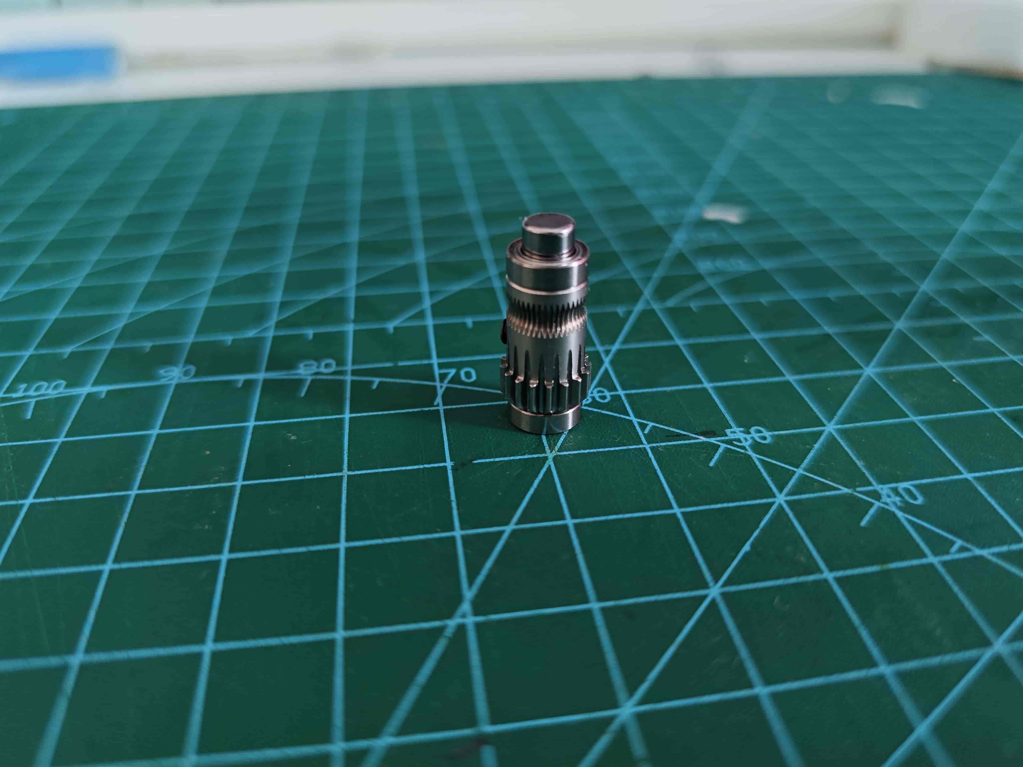
Insert the bmg extruder wheel with the grub screw hole facing the direction shown.
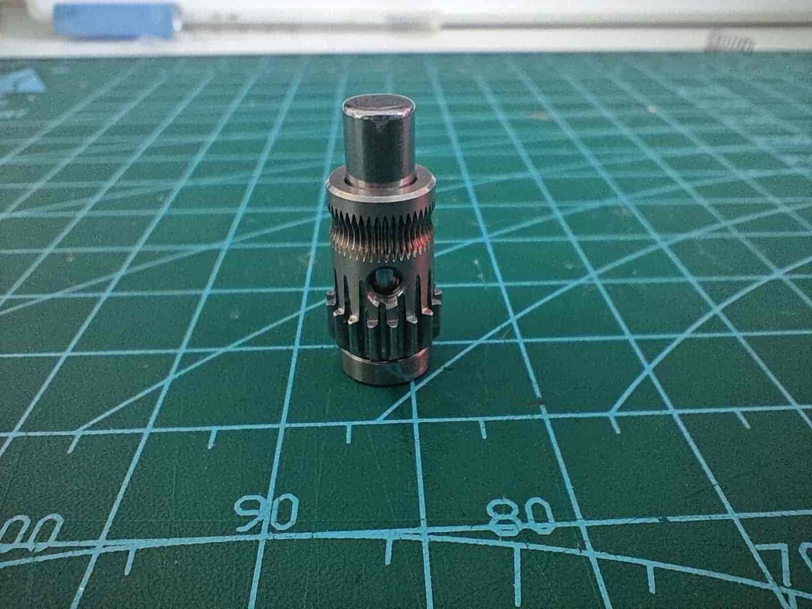
Use a hex wrench to install the grub screw into the bmg's grub screw hole.
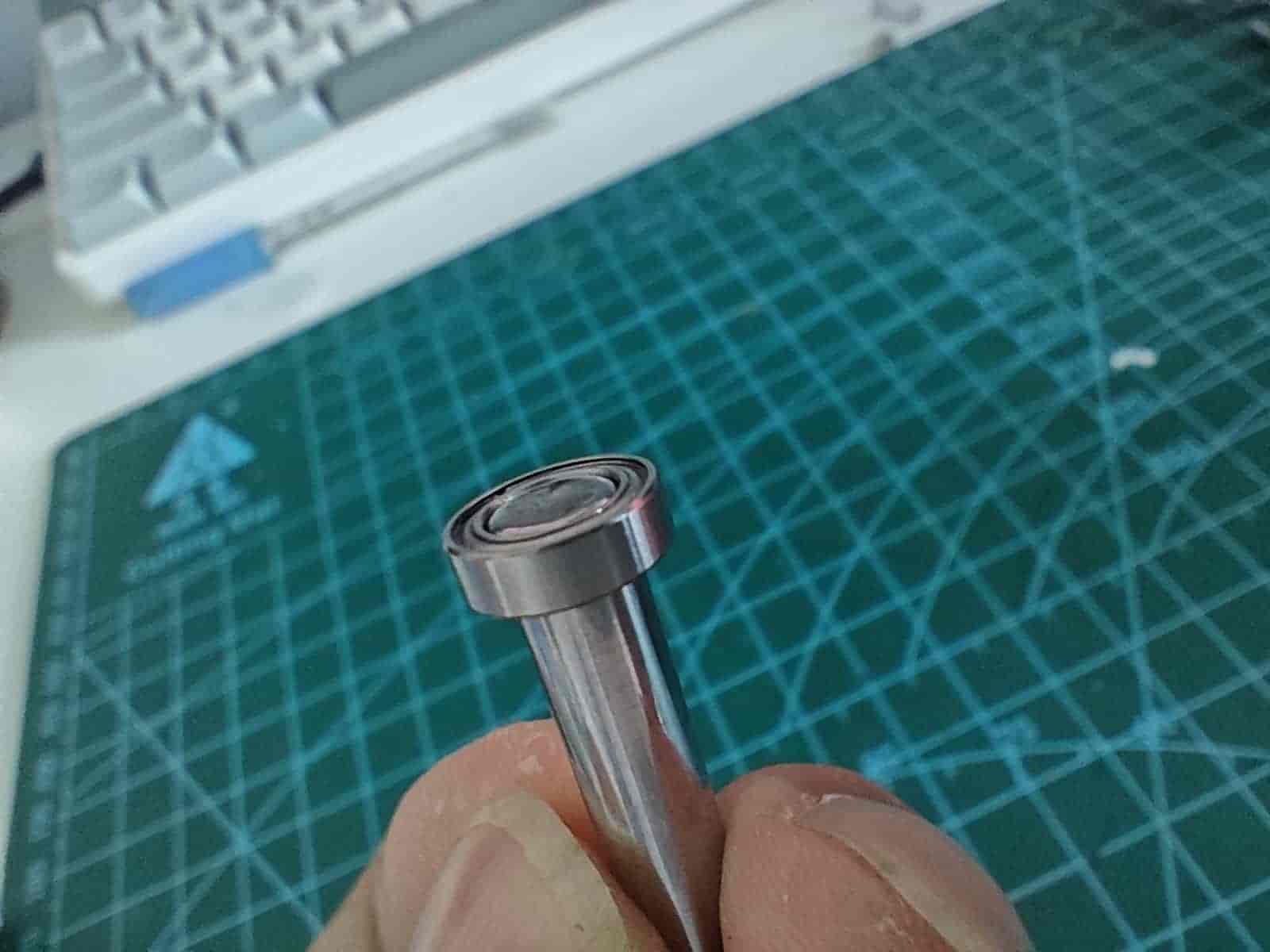
Install the top bearing so it fits flush with the bmg extruder wheel.
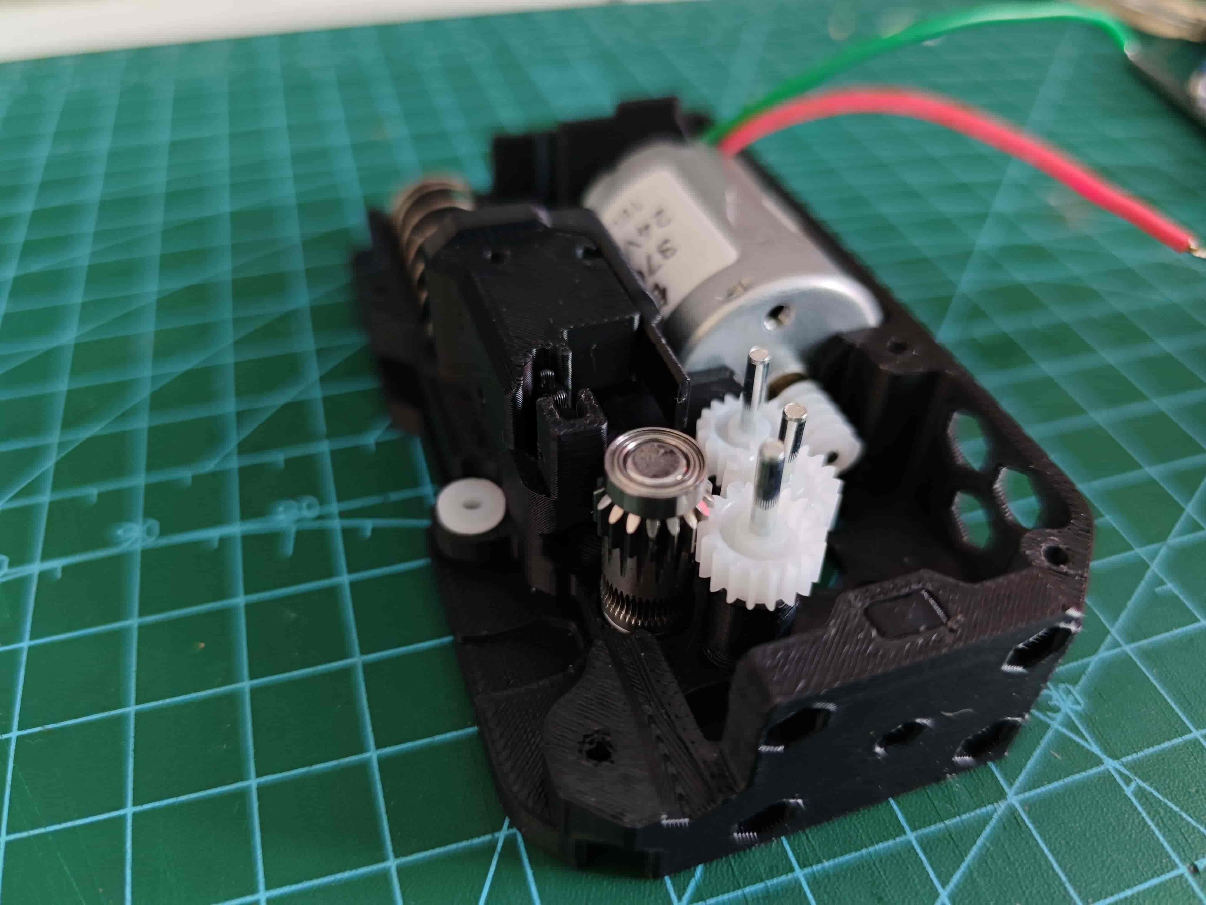
Place the assembled bmg drive wheel into the back cover with the gear facing up as shown.
Assemble BMG Driven Wheel
Insert two needle bearings into the remaining bmg extruder wheel without a grub screw hole.
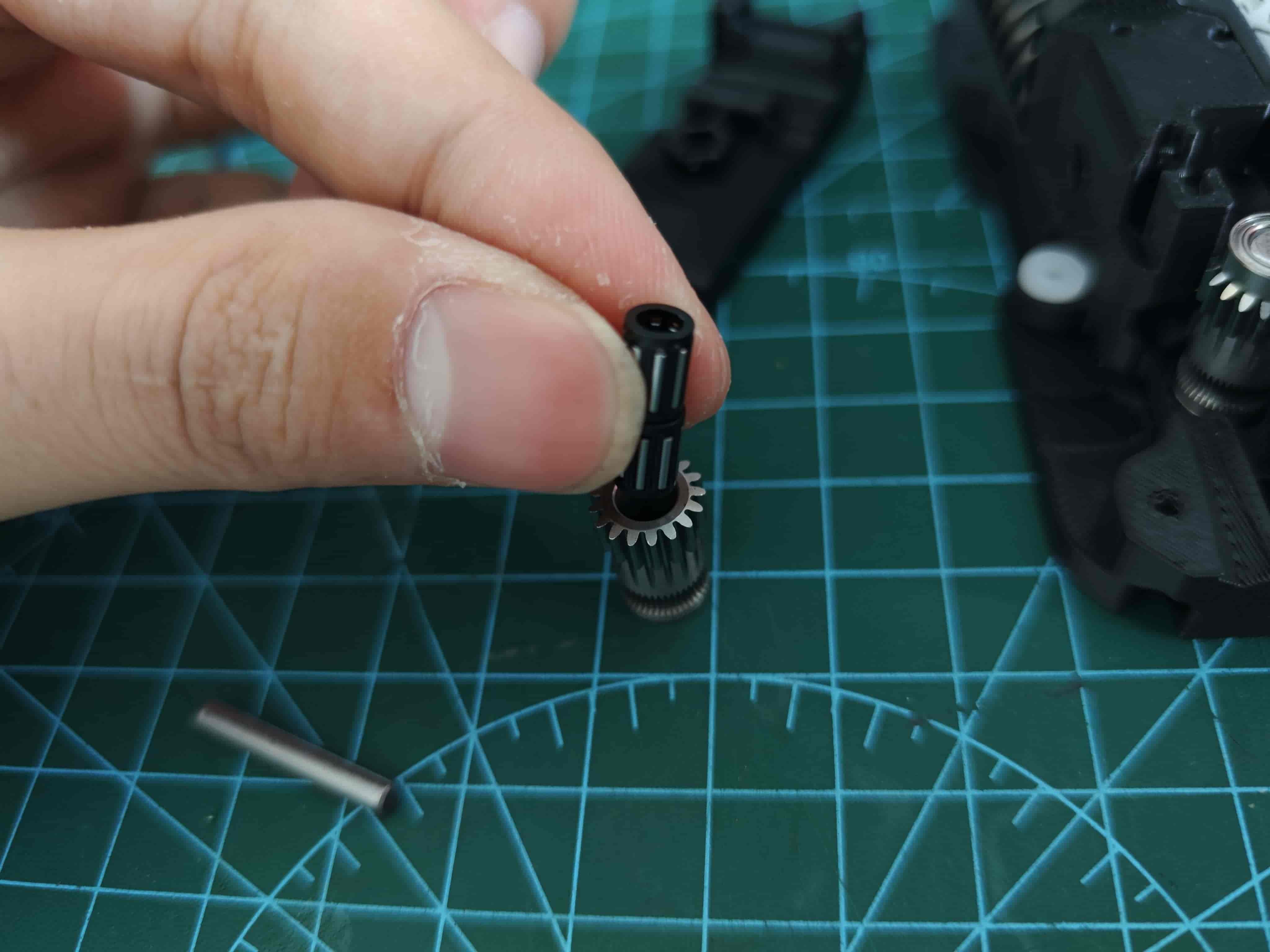
Place it into the wrench, pay attention to the installation direction, then insert the shaft included in the bmg gear set.
Lubricate the Gears
I use Hutou's "Car Door Hinge and Slideway Grease." You can choose other greases, but do not use lubricating oil.
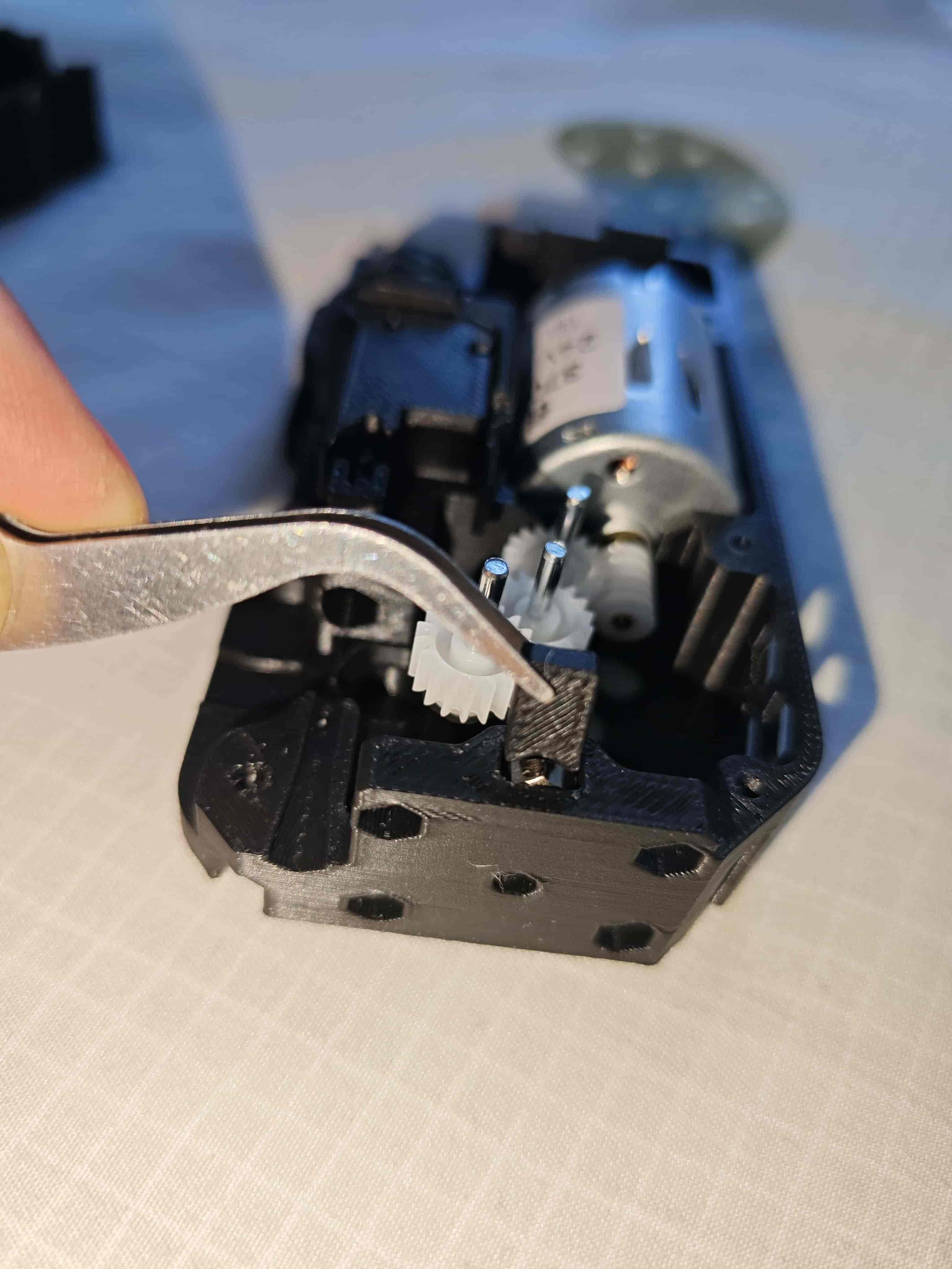
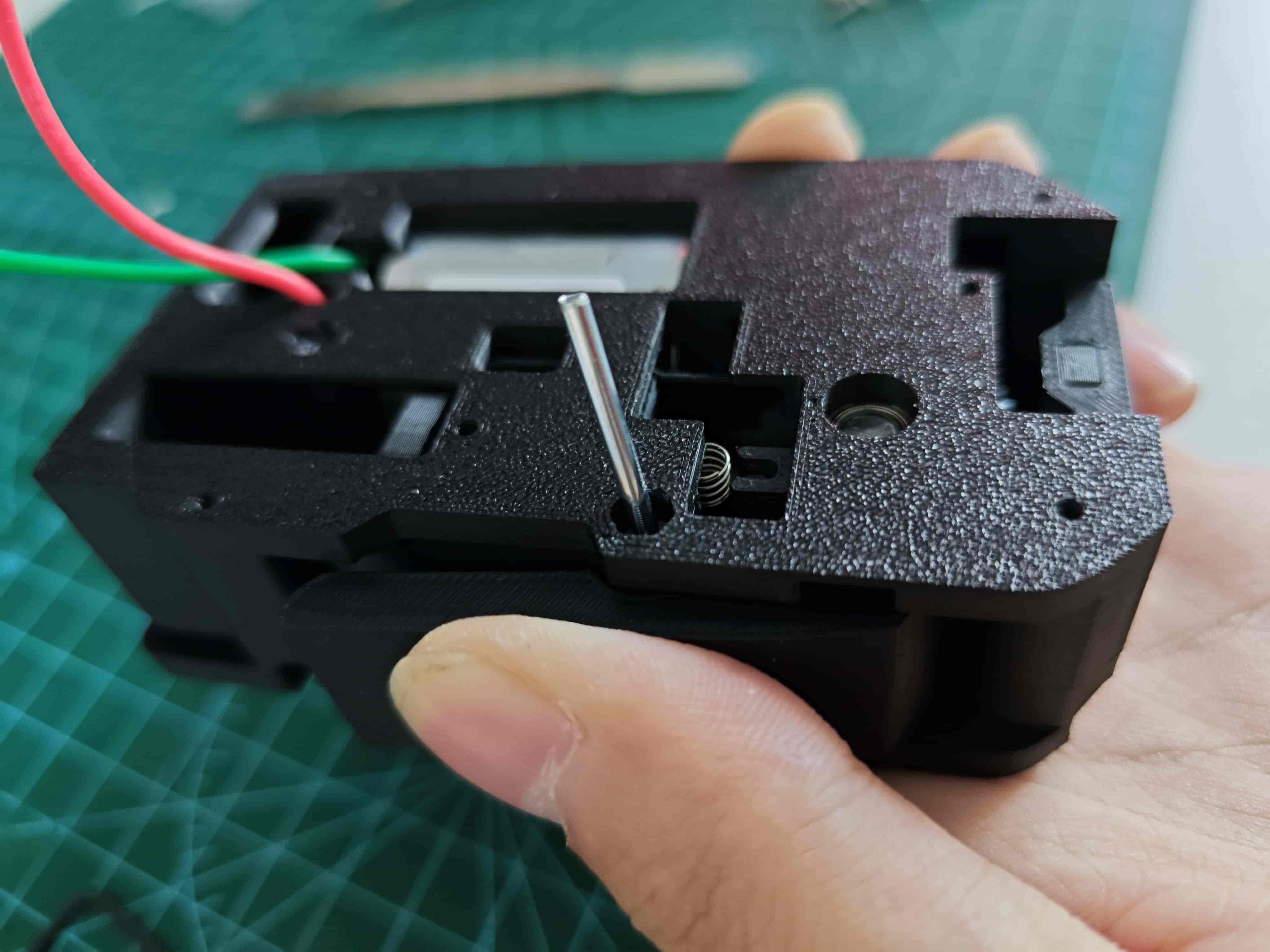
Insert Steel Ball Spring
Close the Middle Frame
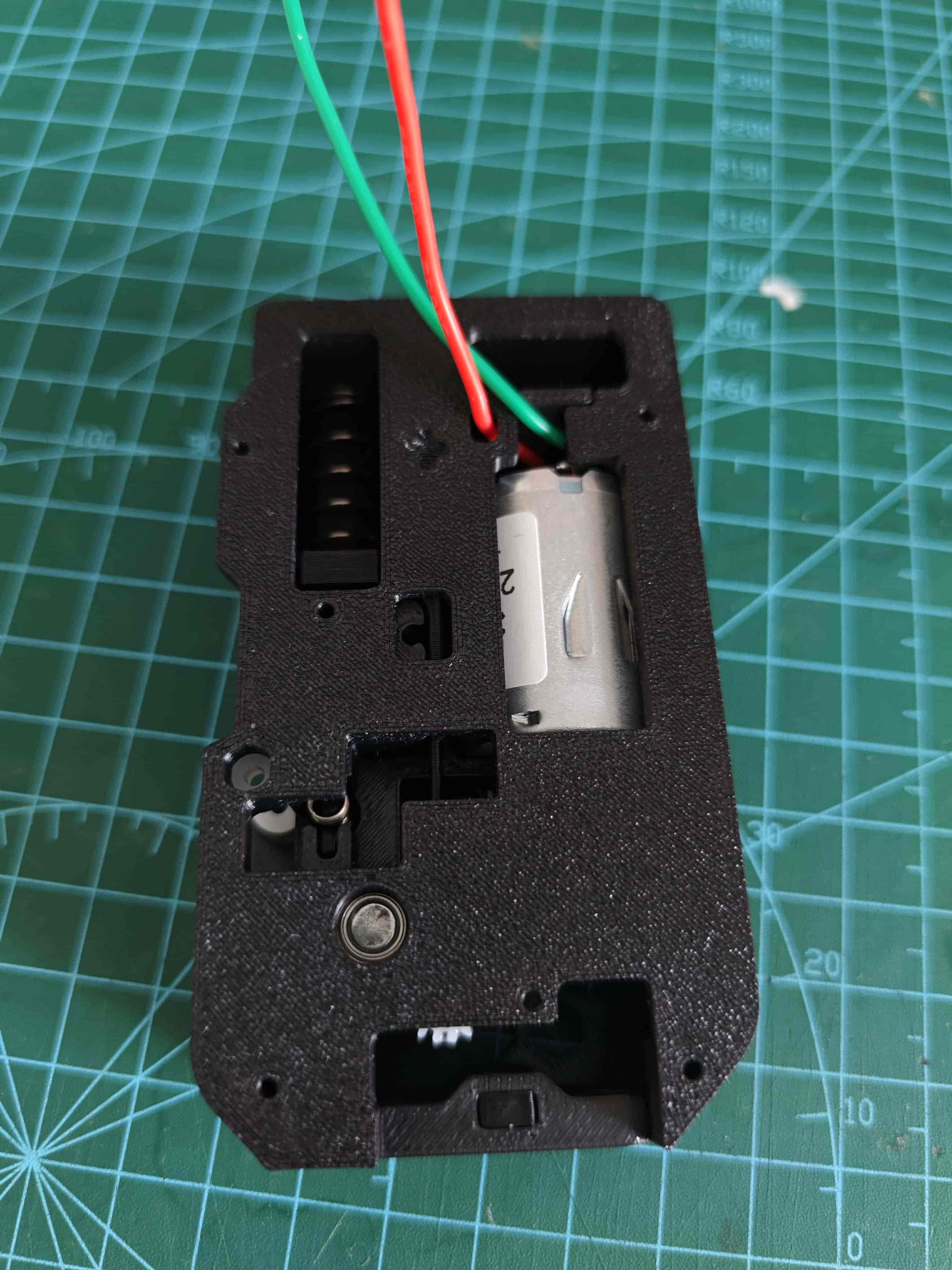
Fix the middle frame with m2*8 screws.

Install the Wrench
Place the wrench into the assembly, insert a 0.6*4x10mm spring.
TIP
If your tubing and filament rack have high resistance, or if you are using a P1 printer, use this model to pad inside the wrench spring slot to increase grip force.
Press down on the wrench and insert a 2*20 shaft to fix the wrench.
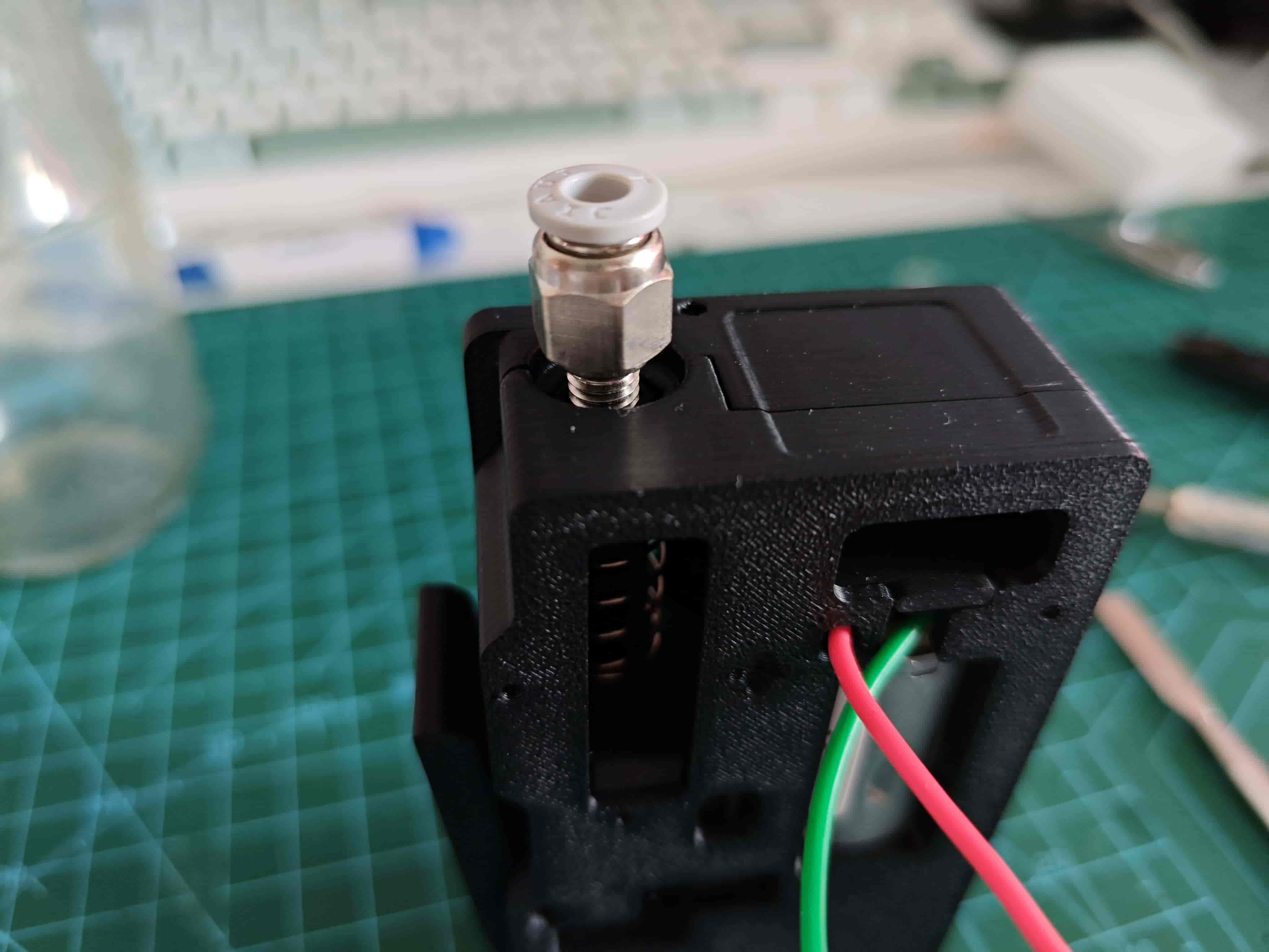
Install Pneumatic Fitting on Buffer
Screw the pneumatic fitting into the buffer.
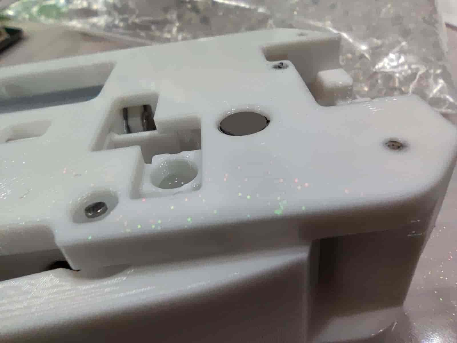
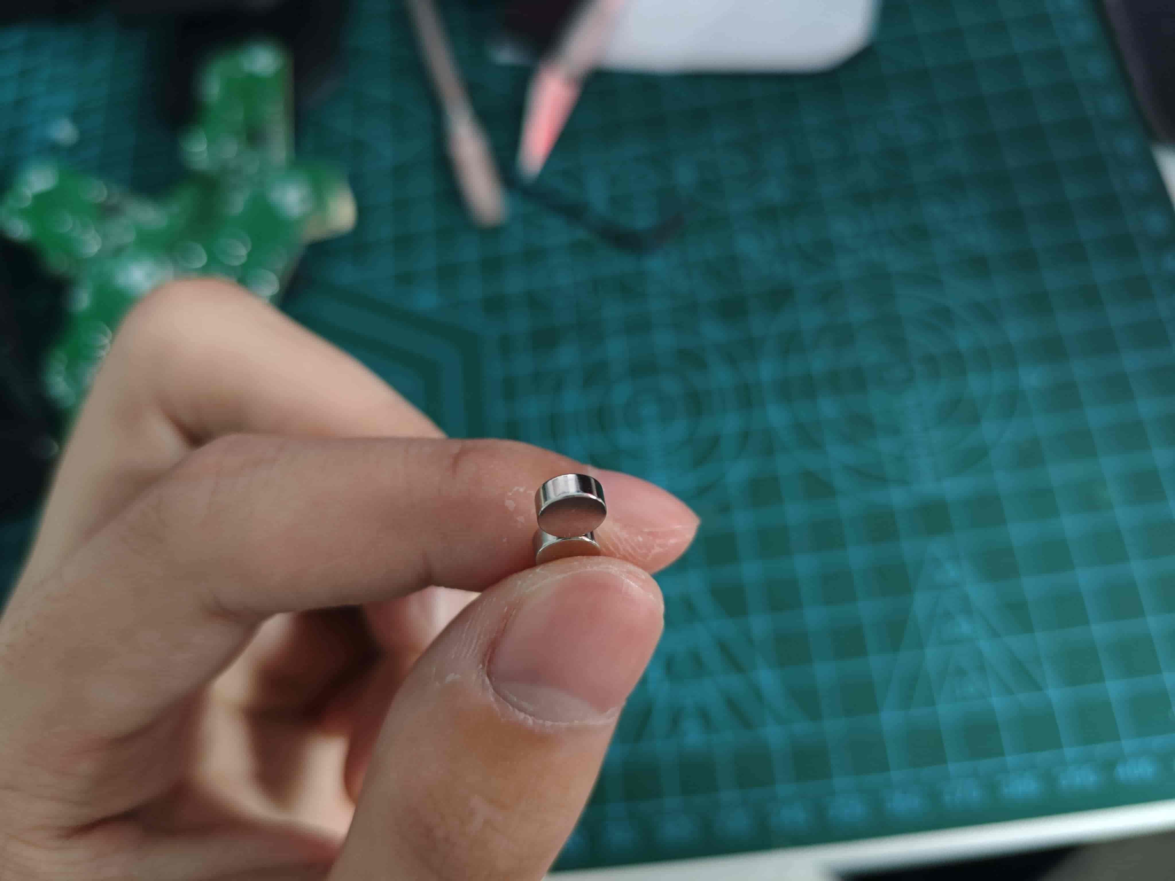
Insert Radial Magnet
Place the radial magnet into the magnet hole of the middle frame, with the magnet slightly below the frame.
This image is taken from the 370x version, but it is the same.
How to Distinguish Axial Magnets and Radial Magnets
Radial magnets attract stronger horizontally and can rotate freely when attracted sideways.
Suggestion
At this point, insert filament, power the motor with a 12v~24v power supply to test if the filament can be pulled, if the magnet rotates, and to evenly spread the grease.
TIP
You can insert an optical fiber into the small hole beside the buffer, cut it flush at the bottom for light guidance.
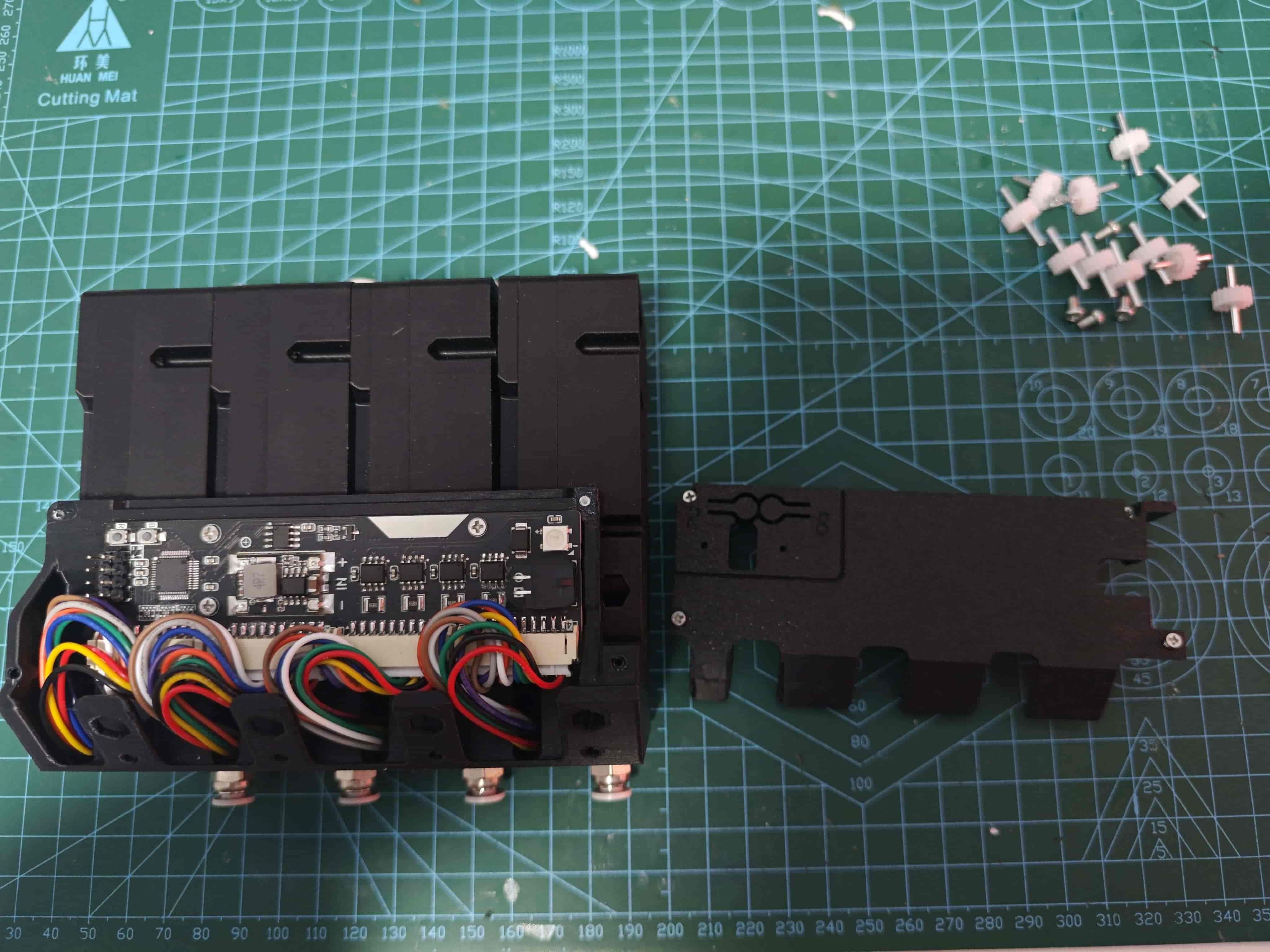
Install Circuit Board and Test
Installation
Place the secondary board onto the middle frame with the photointerrupter facing down, secure it with two m2*8 screws.
Fix the front cover to the middle frame with four m2*8 screws.
Connect the secondary board to the main board with a flat cable.
The main board connects to the computer via a USB-to-TTL module; only power and ground need to be connected, or you can use the exact wiring used during firmware flashing.
Testing
My photos are of the fully assembled finished product with the same effect. It's recommended to test one channel first to avoid unnecessary troubles.
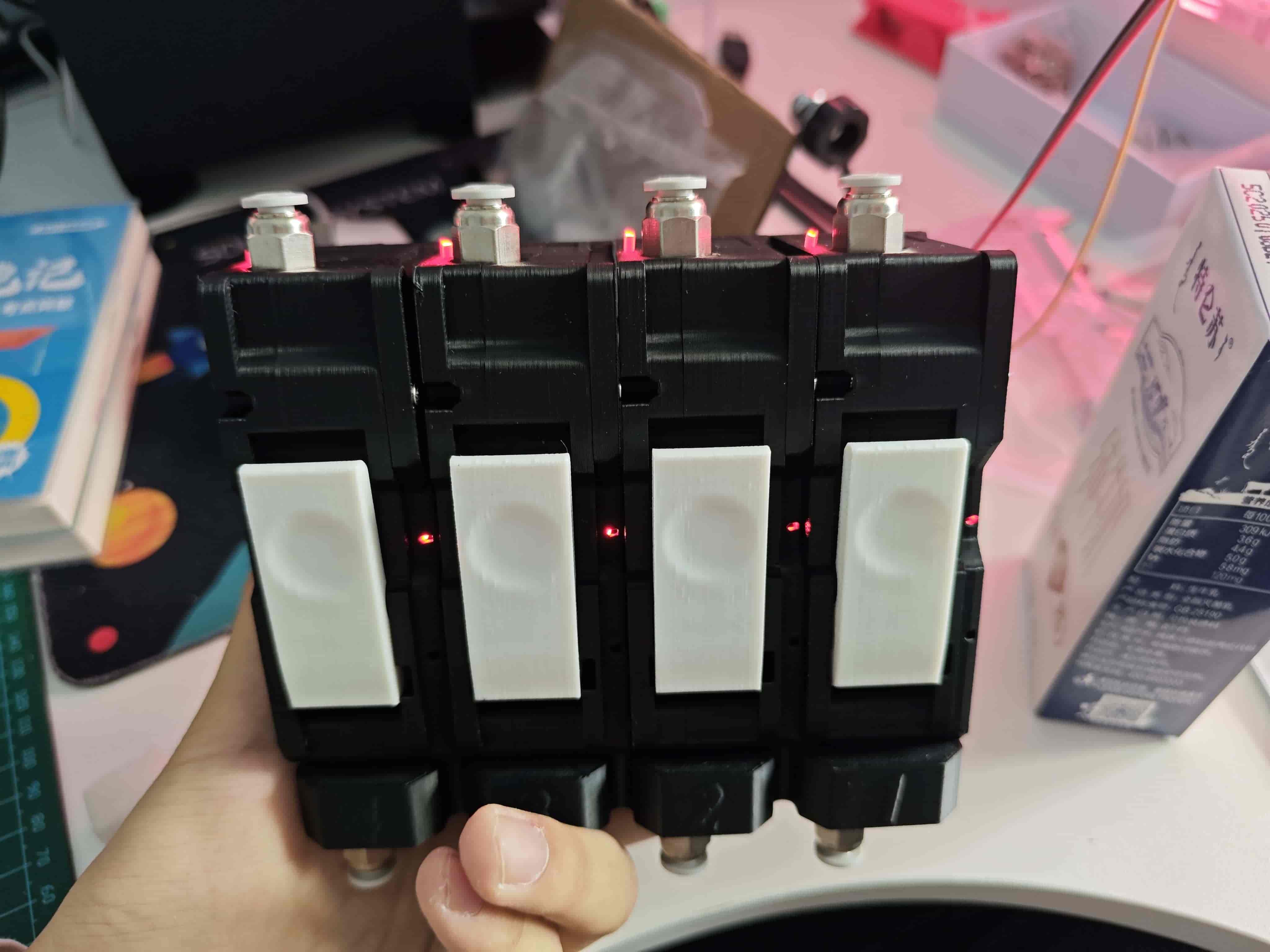
Power on with no action shows the following (main board is not in the photo, indicated by a red LED):
Secondary board WS2812 is red, buffer light is on, filament online light is off.
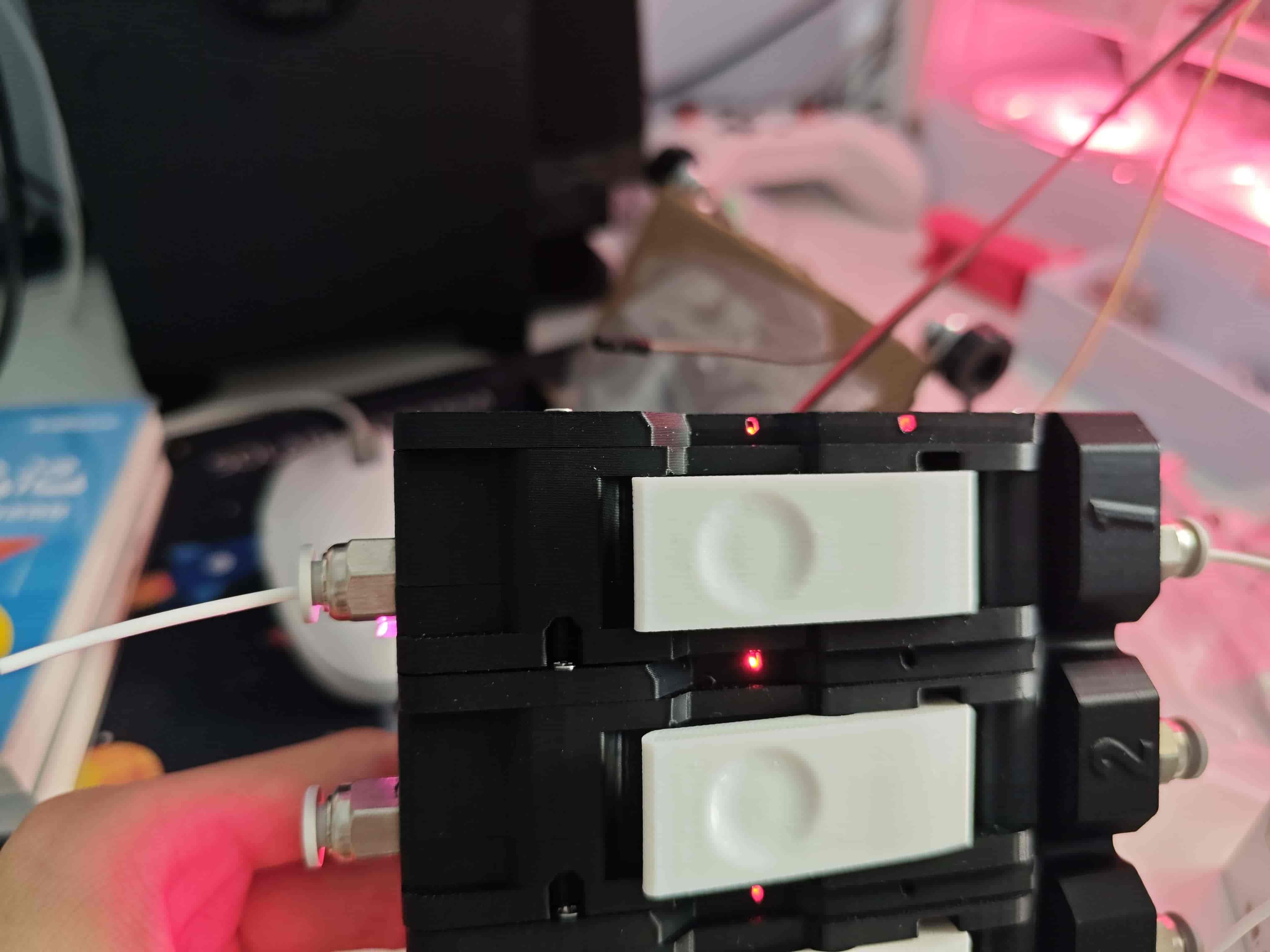
Press the wrench, insert filament, release the wrench, it looks like this:
Secondary board WS2812 is red, buffer light is on, filament online light is on.
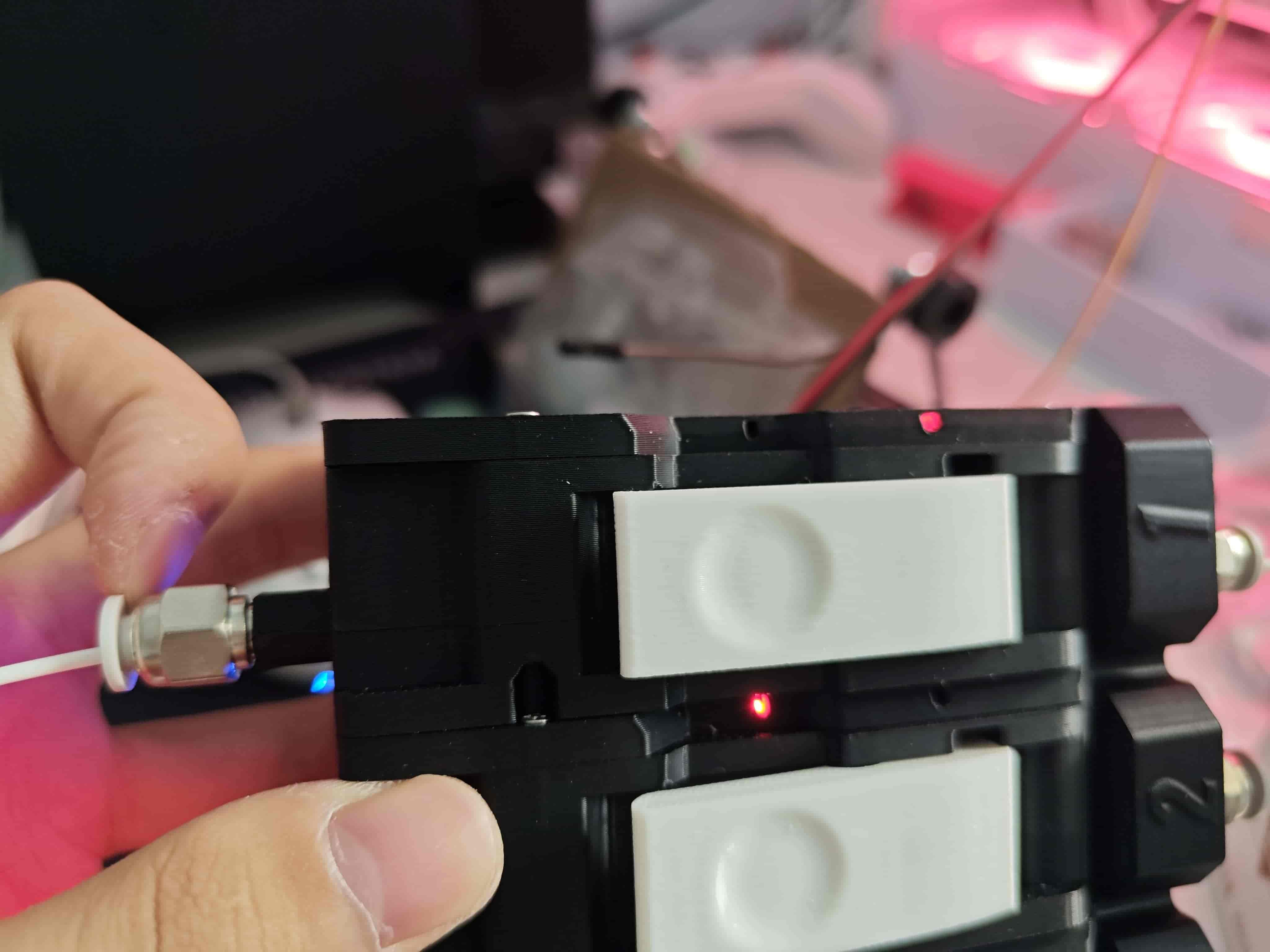
On the basis of the previous step, pull the buffer apart, it looks like this:
Secondary board WS2812 is red, buffer light off, filament online light on.
Install Feeding Component and Circuit Board onto Base
Very simple, follow the picture below.
Use three m2*8 self-tapping screws to fix the main board and four of the same screws to fix the main board cover.
Use m3*14 flat-head screws to fix the feeding component and the base.