

markdown
# Reference for Ground Value
::: info Note
All content on this page is provided by group member `@→`, with minor formatting adjustments by `@wanzi`.
This content applies to the original motherboard and is not suitable for modified or Hall-effect versions.
:::
## Basic Explanation
I don't know much, but I'll share what I do know.
- [What is Ground Value?](https://baike.baidu.com/item/%E5%AF%B9%E5%9C%B0%E6%89%93%E9%98%BB%E5%80%BC/5430067)
- Why use ground value? Because circuits contain many diodes, and the characteristic of diodes is that their voltage drop often falls within a specific range, making the values more intuitive.
- **Ground Value** is also commonly referred to as ground resistance, but it is not a resistance value. Instead, it is the voltage drop of a diode to ground in the circuit, measured in volts (V). The reason it's called ground resistance is unclear—you'd have to ask those in the repair field. Typically, this value is read without units, e.g., 0.450V is referred to as 450.
- Note that factors like chip manufacturing processes, temperature, diode type, and the voltage output of different multimeter probes can cause fluctuations in this measurement. Therefore, the values provided here are for reference only. Actual values should be compared with other pins on the chip. How to get the most accurate value? You can measure and record before soldering. Typically, highly integrated chips have lower values, such as CPUs (usually 0.2V+), silicon diodes (0.6-0.7V), silicon transistors (0.7-1.2V), and Schottky diodes (0.2-0.4V).
## How to Measure Ground Value
- To measure ground value, set the multimeter to the **diode test mode**. Many multimeters combine the diode test and continuity test modes, where lower values trigger a beep and higher values display the voltage drop. Some require switching to the continuity test mode and pressing a function key. Pay attention to the units when using.
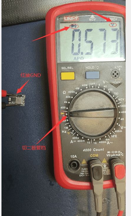
- As shown in the image, connect the red probe to the PCB's GND (e.g., the negative terminal of the 24V input MX3.0 connector) and use the black probe to touch the test point (**reverse the probes for negative voltage measurements, such as -5V or -12V in a computer power supply**).
- If the test point is connected in series with a capacitor, the value should be infinite (OL). If the point is connected to multiple chips, the value on any point of the line will be the same and represent the lowest value among the connected chips.
## Measurement
### Example
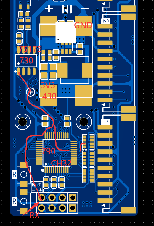
For the pin header shown in the image, we connect the red probe to any GND on the PCB (e.g., the negative terminal of the 24V input MX3.0 connector) and use the black probe to measure RX. Possible readings include **730, 790, 430, 0.000, OL**. As mentioned earlier, this value reflects the voltage drop from the test point through the chip to GND, showing the lowest value among the connected chips. From the circuit diagram, we know the RX point is connected to pin 31 of the CH32, pin 1 of the 75176, and pin 3 of the pull-up resistor RN3. Below is an analysis of these values.
- **730**
This is the value of the 75176 chip, indicating no open circuit between the point and the chip, and that the 75176 is properly connected to GND without abnormalities. However, it does not confirm whether the point is open or has cold solder joints with pin 31 of the CH32 or pin 3 of RN3, or whether the chip pins are bridged. Test these points to see if their values match or are 730.
- **790**
This is the value of the CH32. If the minimum value of 730 is not displayed, it may indicate an open circuit. Similarly, RN3's value should match or be 730.
- **430**
This is the ground value of 3V3, indicating a short between the point and 3V3. Possible causes include solder bridging between pin 3 of RN3 and 3V3.
- **0.000**
Short to ground.
- **OL**
Open circuit between the point and the chip.
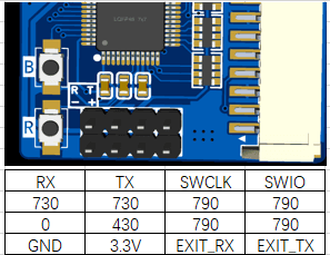
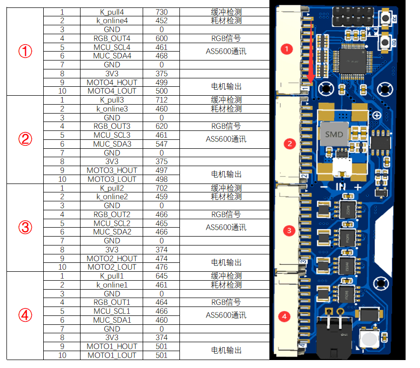
### Pin Header Ground Value Reference
- My reference values:
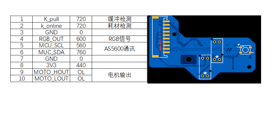
### 2.0 Interface Ground Value Reference
- My reference values:
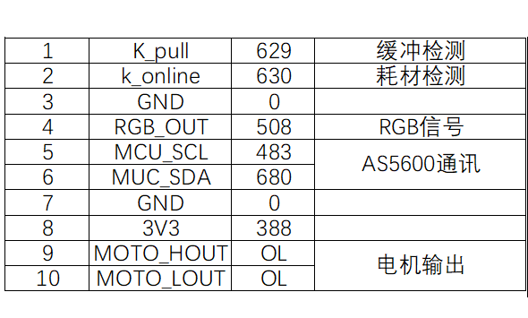
- Group member's reference values:
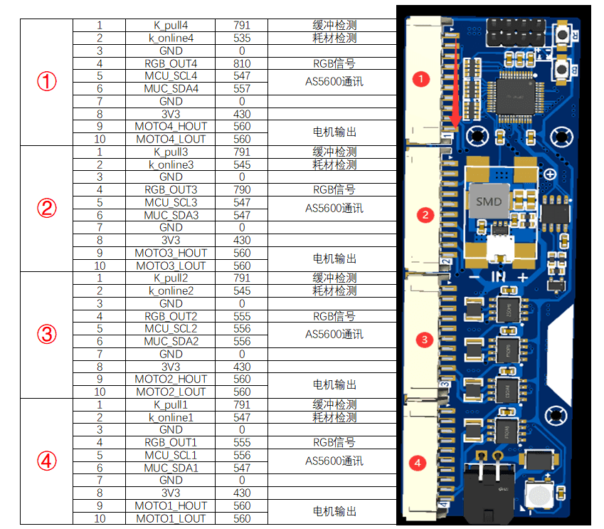
### Small Board Ground Value Reference
- My reference values:
- Group member's reference values:
- What if my values don't match any of the above? Just as people have different physiques, chips vary too. Minor fluctuations are normal. Even if the value exceeds 1.0V or some parts are damaged, as long as there's no short to ground, you can safely power it on and test.
- What if my values match the above, connections are correct, the TTL device is intact, but I still can't flash or unlock/recognize it? Try the "board transplant" method: solder only the CH32 chip and resistor RN3, short the solder points of the B button, and ensure only the TTL working conditions are met for flashing tests.